Testing Procedures
TT
TT
T
o ao a
o ao a
o a
vv
vv
v
oid the risk of electric shocoid the risk of electric shoc
oid the risk of electric shocoid the risk of electric shoc
oid the risk of electric shoc
k,k,
k,k,
k,
per per
per per
per
sonal injursonal injur
sonal injursonal injur
sonal injur
y ory or
y ory or
y or
death, disconnect power before servicing, unless testingdeath, disconnect power before servicing, unless testing
death, disconnect power before servicing, unless testingdeath, disconnect power before servicing, unless testing
death, disconnect power before servicing, unless testing
requires it.requires it.
requires it.requires it.
requires it.
WARNING
RS2310002 Rev. 1 38
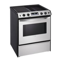
Gas Thermostat
This system uses a thermostat which internally selects
the Bake, Broil, and Clean circuits eliminating the
separate selector switch.
Verify voltage being supplied to the gas thermostat by
measuring voltage at terminal 2 of the gas thermostat,
meter should indicate 120 VAC.
Verify gas thermostat is working correctly by measuring
voltage at BA in bake mode, BR in broil mode, and C in
clean mode. All terminal points should indicate 120 VAC.
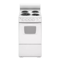
Dial Contacts
1-2
Main COM-NO COM-NC C-BR C-BA 7-9
Low Stop N.S. O X O O O
Bake C
cles N.S. N.S. O X O
Broil Cycles N.S N.S. X O O
Clean Cycles X Below
700° F
X Above
700° F
OOX
NOTE: When switching oven thermostat from broil to
bake always turn fully to OFF first. Otherwise
the broil burner remains on by the thermostat.
1
2
COM
N.C.
N.O.
BR
BA
9
12
7
NO
NC
9BABR
COM
C
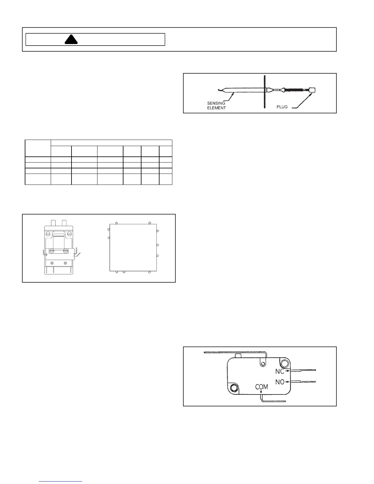
Oven Temperature Sensor
The oven temperature sensor can be checked by using
the "Quick Test Mode" covered in this section of manual
or detail testing can be accomplished as follows.
The oven temperature sensor is mounted in the oven
cavity and electrically connected to the ERC. Following
is approximate resistance.
75°F — 1082 ohms
350°F — 1656 ohms
550°F — 2056 ohms
880°F — 2686 ohms
Sensor resistance can be checked by removing the
sensor interconnect harness plug from the ERC and
inserting ohmmeter leads into the harness connector
plug. A resistance reading of approximately 1100 ohms
should be indicated at ambient room temperature
(75°F.). If a higher resistance is indicated then remove
sensor from oven, disconnect sensor from harness at
plug, and recheck sensor resistance to assure that the
problem is in the sensor and not in the interconnect
harness or due to a bad connection.
NOTE: Sensor resistance will increase if held in your
hand.
Cooling Fan Motor
Fan may come on at any time to cool components
down.
1. Turn off power to oven.
2. Disconnect wires from motor terminal connectors.
3. Attach ohmmeter leads to terminal tabs on motor.
4. A resistance reading of 15-30 ohms should be
indicated but may vary with each motor tested. This
test is to check the motor winding for an open or
shorted winding. If zero or infinite ohms is indicated,
the motor winding has failed and the motor must be
replaced.
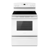
Clean Circuit Manual Latch Switch
The latch switch is a single pole, single throw switch.
When the door latch is moved to the far right or locked
position, the switch contacts COM-NO provide a
connection path from gas thermostat to the clock timer,
terminal AT3.
The switch contacts can be checked as follows:
1. Turn off power to range.
2. Disconnect the switch wire leads and check the
COM-NO and COM-NC contacts for continuity.
3. When the door latch is in the left or unlocked
position, the COM-NO contacts should be open and
the COM-NC contacts should be closed.
4. Move the door latch to the far right or locked position.
The COM-NO contacts should be closed and the
COM-NC contacts should be open.