A–3 RS2310002 Rev. 1
Service Information
The LED Clock with Minute and Clean Timer is designed
to provide clock and timer functions as well as a timed
relay for cleaning operation. This clock consists of a
display, relay, and all cicuitry which are housed in a
single component.
Functions for the clean cycle to operate correctly consist
of latch switch, clock, and thermostat to work in series
with each other to operate the clean cycle. If one of the
components is not operating correctly, this will effect the
operation of cleaning cycle.
Test Procedure
Performance of this clock is very simple to verify proper
operation. Follow the procedures below:
Clock Display Not Operating
1. Verify voltage is present at Line 1 and Line 2
terminals of the clock.
2. If no voltage is present, verify wire connection are
properly in place, and check wire continuity.
3. Replace clock if voltage is present at clock and no
display is present.
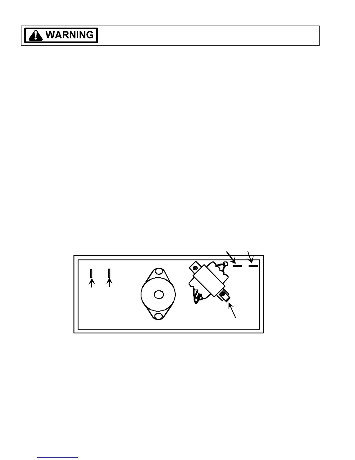
Clean Operation of Clock
1. Verify voltage to AT3. If no voltage check latch switch
operation, and thermostat operation..
2. Verify voltage at AT4 when programmed for clean. If
no voltage, replace the clock.
Testing Procedures
TT
TT
T
o ao a
o ao a
o a
vv
vv
v
oid the risk of electric shocoid the risk of electric shoc
oid the risk of electric shocoid the risk of electric shoc
oid the risk of electric shoc
k,k,
k,k,
k,
per per
per per
per
sonal injursonal injur
sonal injursonal injur
sonal injur
y or death,y or death,
y or death,y or death,
y or death,
disconnect po disconnect po
disconnect po disconnect po
disconnect po
werwer
werwer
wer
before servicing, unless testing requires it.before servicing, unless testing requires it.
before servicing, unless testing requires it.before servicing, unless testing requires it.
before servicing, unless testing requires it.
Refer to wiring diagram for thermostat switch schedule.
AT4
AT3
LINE 1(L)
LINE 2(N)
GROUND