Testing Procedures
TT
TT
T
o ao a
o ao a
o a
vv
vv
v
oid the risk of electric shocoid the risk of electric shoc
oid the risk of electric shocoid the risk of electric shoc
oid the risk of electric shoc
k,k,
k,k,
k,
per per
per per
per
sonal injursonal injur
sonal injursonal injur
sonal injur
y ory or
y ory or
y or
death, disconnect power before servicing, unless testingdeath, disconnect power before servicing, unless testing
death, disconnect power before servicing, unless testingdeath, disconnect power before servicing, unless testing
death, disconnect power before servicing, unless testing
requires it.requires it.
requires it.requires it.
requires it.
WARNING
RS2310002 Rev. 1 40
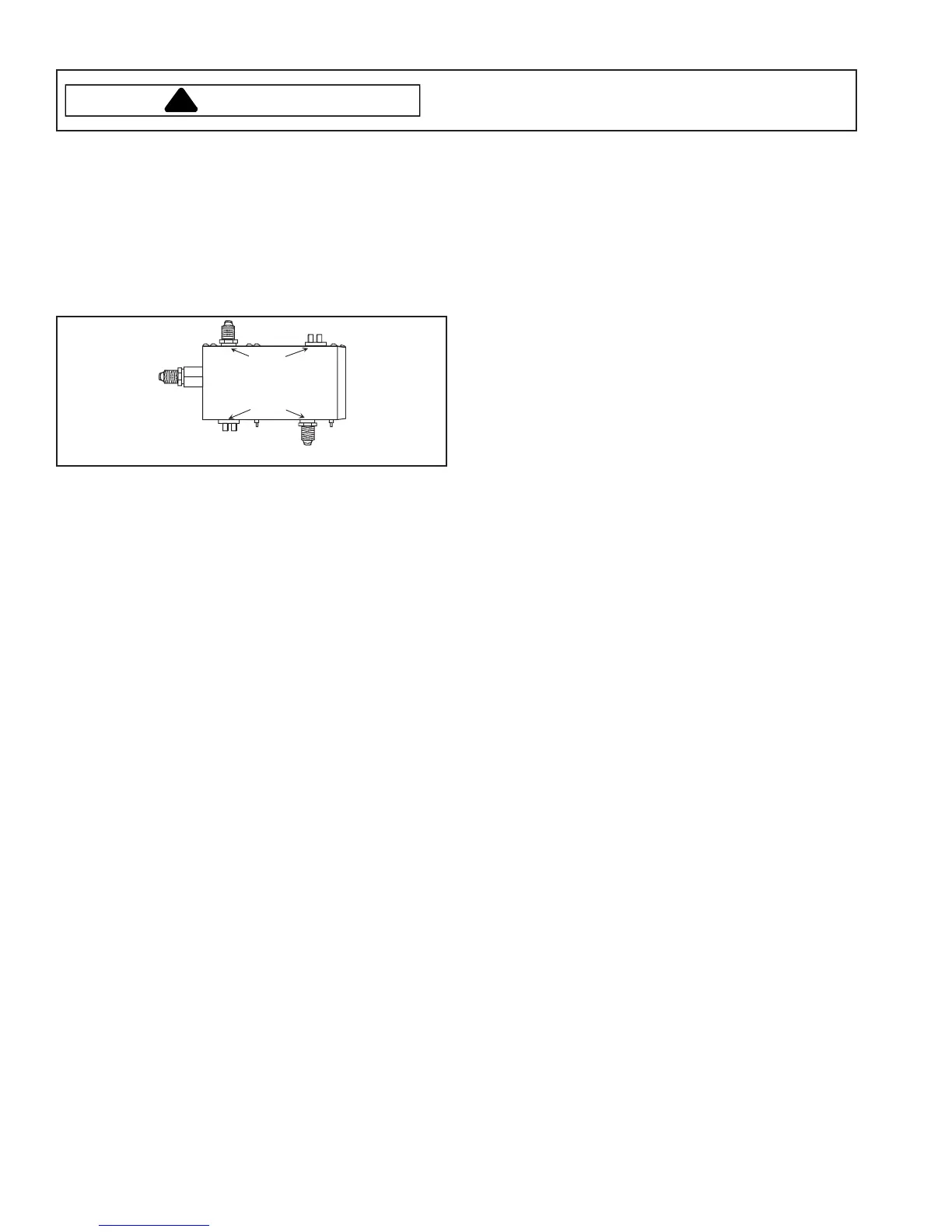
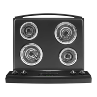
Gas Valve
Bake and broil dual gas valves supply gas to the bake
and broil burners. Valves contain bimetal arms attached
to the valve seats. These arms are wrapped with a small
electric heater coil. When current range of
approximately 3.3 - 3.6 amps flows through the bake or
broil circuit, bimetal arm is heated. Heating causes the
arm to bend, allowing gas to flow and be ignited by the
burner ignitor.
Broil
Bake
Typical Gas Valve
The bimetal arms can be checked for continuity using
the following procedure.
1. Disconnect power to oven. Remove gas valve
wiring.
2. Access valves by removing control panel glass and
control panel mounting bracket.
3. Set ohmmeter to low ohms scale. Attach meter leads
to the two gas valve terminals facing rear of oven.
4. Meter should indicate low ohms or continuity.
5. Repeat on two gas valve terminals facing front of
oven.
6. If meter indicates infinite ohms or an open heater
coil, gas valve must be replaced.
NOTE: Do not apply 120 VAC to valve. Applying
120 VAC to valve will render valve
inoperative.
Spark Module 4 + 0
When properly operating, the spark module repeatedly
produces a spark at the ignitor accompanied by a sharp
snapping sound.
1. Turn off gas and power supply to unit.
2. Check wiring diagram to verify all terminals and wire-
connections are correct and tight with no cuts in the
wiring.
3. Prepare to measure voltage on spark module from
terminal L to N.
4. Turn power supply back on.
5. Turn top burner to
LITE
position.
6. If no voltage is present on the meter, this will indicate
the electrical circuit is interrupted before the spark
module
7. If voltage is present, then check ignitor.
8. If ignitors are ok; then replace spark module.
Top Burner Spark Ignitors
All units have an electrode for each burner. When any of
the burner valves are turned to the LITE position, the
spark switch on the valve connects supplying voltage to
the spark module. This activates the module that
produces the spark at the ignitor electrode to light the
burner.
1. Turn off gas and power supply to unit.
2. Check wiring diagram to verify all terminals and wire-
connections are correct and tight.
3. Disconnect high voltage spark ignitor leads from
terminals on the spark module.
4. Attach one meter lead to a good ground and the
other lead connected to ignitor terminal wire. If
continuity is indicated, ignitor or wire is shorted to
ground. If no continuity is indicated proceed to next
step.
5. Attach one lead to ignitor terminal wire and the other
lead to the tip of ignitor. If no continuity is indicated
ignitor or wire is open. If continuity is indicated ignitor
is good.
Spark Switch Test
Each spark switch is connected in parallel with spark
ignition circuit. One terminal on each switch is
connected to 120 VAC, while the other terminal
connects to the "L" on the spark module. Terminal "N" of
the module connects to the common or neutral side of
the AC line. The spark switch is located on the stem of
the top burner valve.
1. Turn off gas and power supply to unit.
2. Check wiring diagram to verify all terminals and wire-
connections are correct and tight.
3. Attach meter leads to switch terminals.
4. Turn switch to
LITE
position. Meter should indicate
zero ohms or closed contacts. Infinite ohms or open
contacts should be indicated in all switch positions
except
LITE
.