EasyManua.ls Logo

Ametek Sorensen SGI Series - Table 2-1. Maximum AC Current Ratings, PFC Models; Table 2-2. Maximum AC Current Ratings, Non-PFC Models; Table 2-3. Input;Output Connectors

Ametek Sorensen SGI Series
120 pages
To Next Page IconTo Next Page
To Previous Page IconTo Previous Page
Loading...
Sorensen SGI Series Installation
M550221-01 Rev U 2-5
Model Ratings
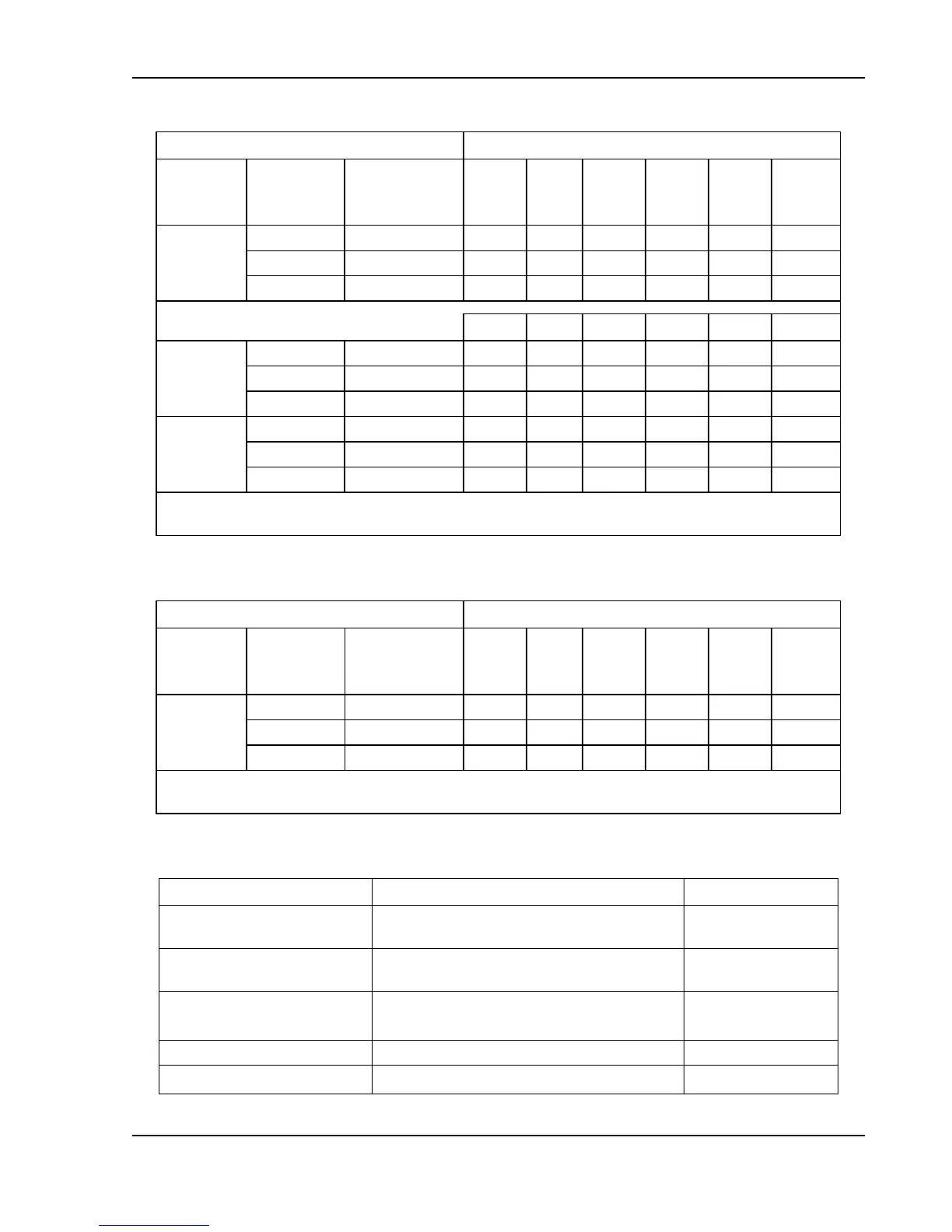
Input Line Current, A (RMS)*
Voltage
Model
AC Input
Option
Code
Input
Voltage,
VAC
5 kW
10 kW
15 kW
20 kW
25 kW
30 kW
40V-1000V
C
208/230
20
39
59
79
98
118
D
380/400
11
22
32
43
54
65
E
440/480
9
19
28
37
47
56
4 kW
8 kW
12 kW
5 kW
10 kW
15 kW
10V-15V
C
208/230
16
32
47
N/A
N/A
N/A
D
380/400
9
17
26
N/A
N/A
N/A
E
440/480
7
15
22
N/A
N/A
N/A
20V-30V
C
208/230
N/A
N/A
N/A
20
39
59
D
380/400
N/A
N/A
N/A
11
22
32
E
440/480
N/A
N/A
N/A
9
19
28
* AC input current could vary as a result of actual power factor; refer to specifications section for
power factor dependency
Table 21. Maximum AC Current Ratings, PFC Models
Model Ratings
Input Line Current, A(RMS)*
Voltage
Model
AC Input
Option
Code
Input
Voltage,
VAC
5 kW
10 kW
15 kW
20 kW
25 kW
30 kW
40V-800V
C
208/230
24
47
71
95
118
142
D
380/400
13
27
40
54
67
81
E
440/480
12
24
36
49
61
73
* AC input current varies depending on actual power factor; refer to specifications section on power
factor
Table 22. Maximum AC Current Ratings, Non-PFC Models
Connector
Function
Connection
L1 AC, L2 AC, L3 AC,
Chassis - GND
AC input power; see Table 24
AC mains 3-phase
input
Pos. Bus Bar,
Neg. Bus Bar
DC output power; see Table 25
User load
Analog Interface
Connector (J1)
Control interface; see Table 35
User controller
Remote Sense Connector
Remote voltage sensing; see Section 3.14
Output load
Parallel In/Out
Parallel operation; see Section 3.16
Master/Slave units
Table 23. Input/Output Connectors

Table of Contents

Related product manuals