Operation Sorensen SGI Series
3-42 M550221-01 Rev U
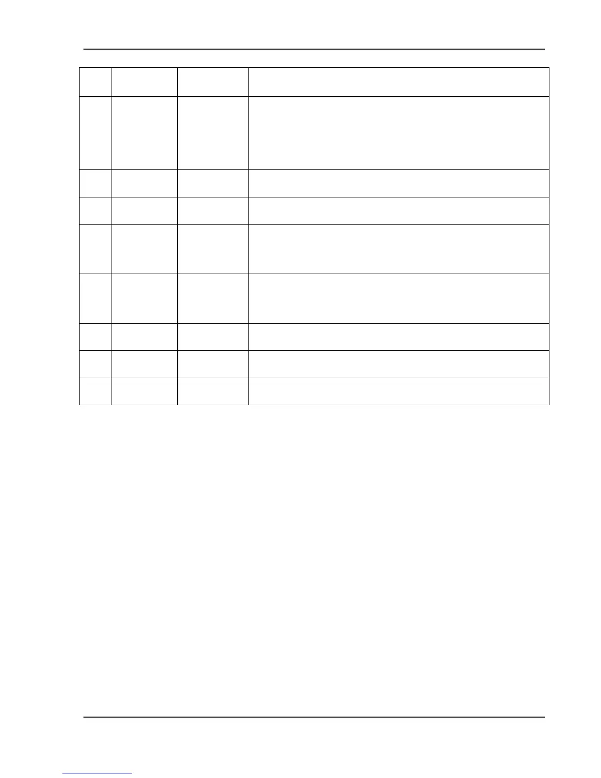
Shutdown fault. This terminal goes to high state in the event of
converter, temperature, overvoltage or bias supply fault. A
7-13.3 VDC signal can be applied to this pin to shutdown the output
of the unit. An 8 VDC minimum output signal is provided into a
10 kminimum load, in the event of an internally generated
shutdown. Circuit return Pin J1-6 (COM). See Section 3.13.3.
Output voltage monitor. 0-10 VDC equals to 0-100% rated voltage.
Minimum load resistance 100 kCircuit return Pin J1-6 (COM).
Voltage programming return. Used with Pins J1-9, J1-15 or J1-21
and must be referenced to Pin J1-6 (COM) circuit common.
1 mA current source for remote voltage programming using
resistance. 0-5 kΩ resistor referenced to Pin J1-4 or Pin J1-20
(VP RTN) will program the output voltage from 0-100%. See
Section 3.11.
1 mA current source for remote current programming using
resistance. 0-5 kΩ resistor referenced to Circuit return Pin J1-23 or
Pin J1-25 (IP RTN) will program the output current from 0-100%.
See Section 3.10.
Current programming return. Used with Pins J1-10, J1-16 or J1-22
and must be referenced to Pin J1-6 (COM) circuit common.
Circuit common connected to Pin J1-6. Same potential as the
negative output terminal.
Current programming return. Used with Pins J1-10, J1-16 or J1-22
and must be referenced to Pin J1-6 (COM) circuit common.
†
With the Remote Isolated Analog Interface control (option), the control ground is isolated from
output power (output negative terminal). See Section 1.2.2 and Section 3.15.
*
Signals not available with Remote Isolated Analog Interface control (option).
Table 3–5. Analog Control Connector (J1), Designations and Functions

 Loading...

