Operation Sorensen SGI Series
3-8 M550221-01 Rev U
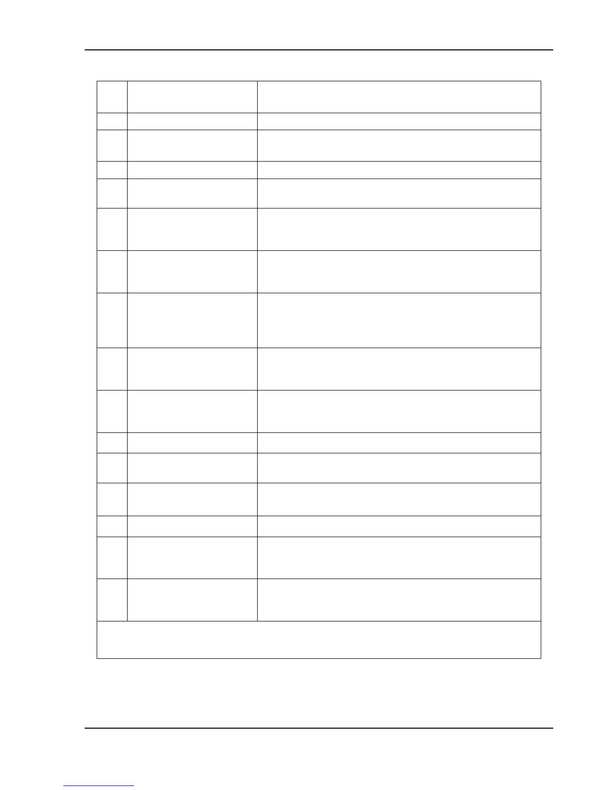
Connection for 3-phase AC.
Connection for safety ground wire.
Positive (+) and negative (–) outputs.
Positive (+) and negative (–) outputs for 800V and
1000V models only.
Parallel Out connector of master unit for configuring
parallel operation of units when connected to Parallel In
connector of slave unit; see Section 3.16.
Parallel In connector of slave unit for configuring parallel
operation of units when connected to Parallel Out
connector of master unit; see Section 3.16.
Remote Analog Interface connector, J1, for
programming and monitoring signals of output, status
indication, and remote shutdown signals; see Table 3–5
for individual pin descriptions.
Input connector, J3, for remote sensing of voltage at the
load to compensate for line drop in load cables; see
Section 3.14.
Input connector,J3, for remote sensing of voltage at the
load to compensate for line drop in load cables, 800V
and 1000V models only; see Section 3.14.
RS-232 connector for remote digital control.
Four–position DIP switch to configure the digital
interface of the unit
Input/Output connector for external auxiliary digital
control signals.
Ethernet connector for remote digital control.
Reset switch to return configuration parameters to
factory default settings; must be depressed until LAN
LED is blinking.
LED indicator: continuously on indicates Ethernet
connection; off indicates no Ethernet connection;
blinking indicates Instrument ID.
Refer to Figure 3-4, Figure 3-7, and Figure 3-10.
†
Refer to the Programming Manual for details on the digital interface.
Table 3–4. Rear Panel Connectors and Controls, Ethernet Option

 Loading...

