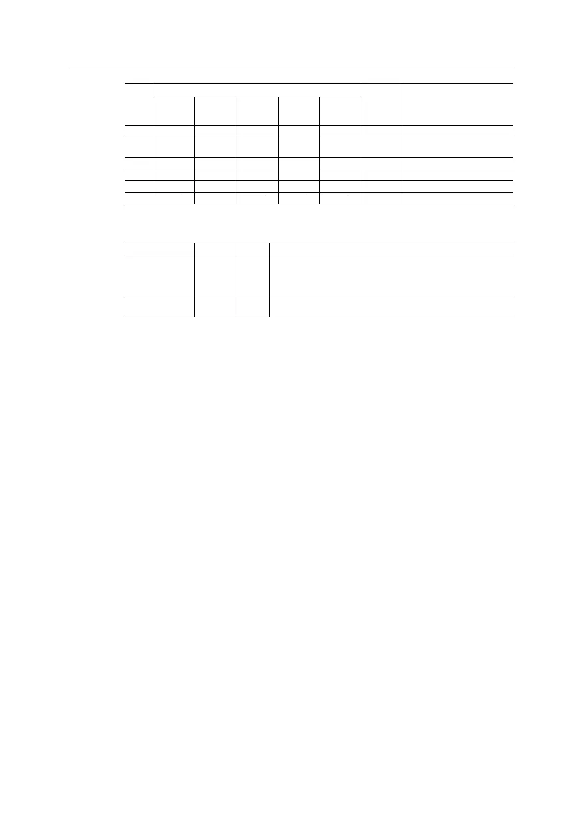
Host Interface 12 (114)
Pin Signal Name Type Notes
Serial
Mode
SPI Mode 8-bit
Mode
16-bit
Mode
Shift
Register
Mode
35 OM2 OM2 OM2 OM2 OM2 I
-
27 MI0/
SYNC
MI0/
SYNC
MI0/SYNC MI0/
SYNC
MI0/
SYNC
O Low at powerup and before
reset release.
2 MI1 MI1 MI1 MI1 MI1 O Connected to 3V3
26 MD0 MD0 MD0 MD0 MD0 O Connected to GND
25 MD1 MD1 MD1 MD1 MD1 O Connected to GND
8 RESET RESET RESET RESET RESET I
-
3.2.2 Power Supply Pins
Signal Name Type Pin Description
GND Power 50
37
12
1
Power and signal ground reference.
3V3 Power 38
13
3.3 V power supply.
Anybus
®
CompactCom
™
M40 Hardware Design Guide HMSI-216-126 EN 2.6