Host Interface 14 (114)
Corresponding LED Placement on Module Fronts
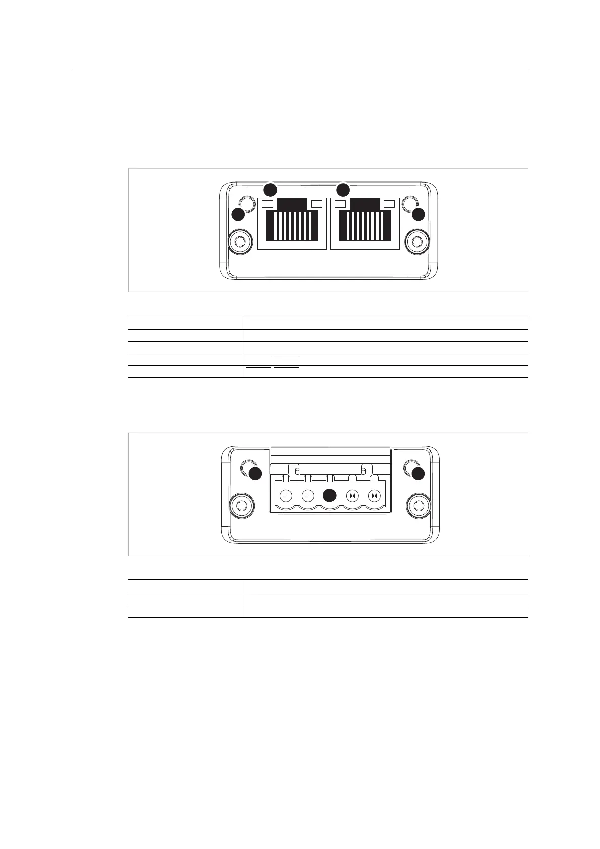
The LED interface signals are shown on the module front as indicated in the pictures below.
See the different Anybus CompactCom 40 Network Guides (app. “Technical Specification”) for
details.
Anybus CompactCom M40 Ethernet modules have four LEDs on the front:
Fig. 3
LED no (in figure) Corresponding signal name in LED interface
1 LED1A/LED1B
2 LED2A/LED2B
3 LED3A/LED3B
4 LED4A/LED4B
Anybus CompactCom M40 modules not supporting Ethernet have two LEDs on the front. The
picture shows the module front of the Anybus CompactCom M40 DeviceNet, but other
modules, e.g. PROFIBUS, have LEDs in the corresponding positions.
Fig. 4
LED no (in figure) Corresponding signal name in LED interface
1 LED1A/LED1B
2 LED2A/LED2B
Anybus
®
CompactCom
™
M40 Hardware Design Guide HMSI-216-126 EN 2.6