Host Interface 16 (114)
Operating Modes
These inputs select the interface that should be used to exchange data (SPI, stand-alone shift
register, parallel or serial) and, if the serial interface option is used, the operating baud rate. The
state of these signals is sampled once during startup, i.e. any changes require a reset in order
to have effect.
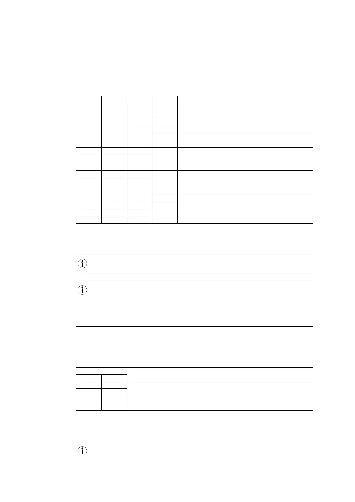
OM3 OM2 OM1 OM0 Operating Mode
LOW LOW LOW LOW Reserved
LOW LOW LOW HIGH SPI
LOW LOW HIGH LOW Stand-alone shift register
LOW LOW HIGH HIGH Reserved
LOW HIGH LOW LOW Reserved
LOW HIGH LOW HIGH Reserved
LOW HIGH HIGH LOW Reserved
LOW HIGH HIGH HIGH 16-bit parallel
HIGH LOW LOW LOW 8-bit parallel
HIGH LOW LOW HIGH Serial 19.2 kbps
HIGH LOW HIGH LOW Serial 57.6 kbps
HIGH LOW HIGH HIGH Serial 115.2 kbps
HIGH HIGH LOW LOW Serial 625 kbps
HIGH HIGH LOW HIGH Reserved
HIGH HIGH HIGH LOW Reserved
HIGH HIGH HIGH HIGH Service Mode
LOW = V
IL
HIGH = V
IH
These signals must be stable prior to releasing the RESET signal. Failure to observe this may
result in faulty behavior.
In an application, where it has to be possible to change an Anybus CompactCom M30 module for
an Anybus CompactCom M40 module, there should be an external pull-up on the OM3 pin to
ensure correct and stable behavior. The reason is that during startup the OM3 will indicate an
M30 mode if it is high. The signal will change to an output signal after startup, and will then be
used either for the serial interface towards the host application or for black channel
communication using an external safety module.
Module Detection
These signals are internally connected to GND, and can be used by the host application to
detect whether a module is present or not.
State Indication
MD0 MD1
HIGH HIGH Module not present
LOW HIGH
HIGH LOW
LOW LOW Module present
LOW = V
OL
HIGH = V
OH
If unused, leave these signals unconnected.
Anybus
®
CompactCom
™
M40 Hardware Design Guide HMSI-216-126 EN 2.6