Host Interface 17 (114)
Module Identification
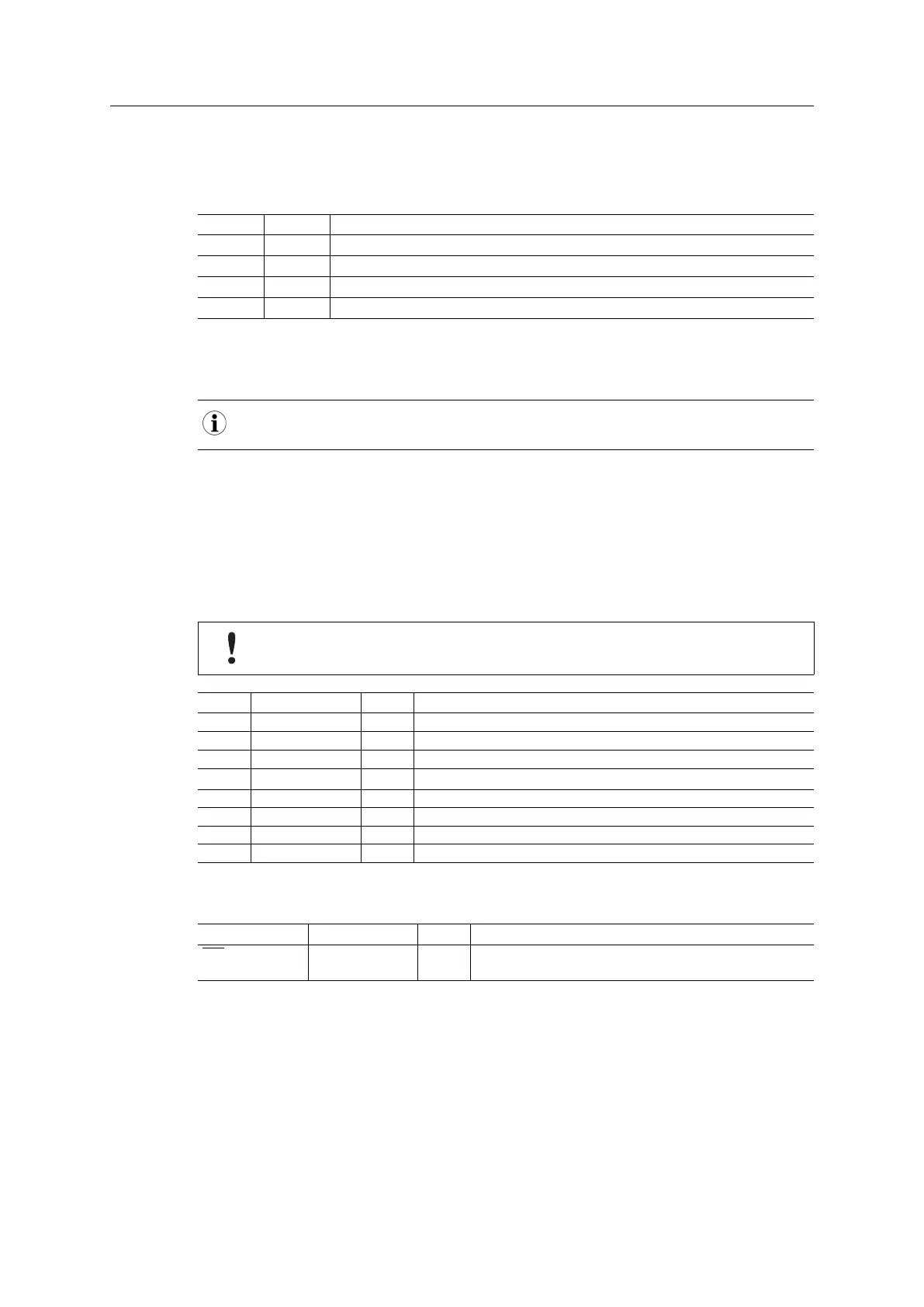
These signals indicate which type of module that is connected. It is recommended to check the
state of these signals before accessing the module.
MI1 MI0
Module Type
LOW LOW Active Anybus CompactCom 30
LOW HIGH Passive Anybus CompactCom
HIGH LOW Active Anybus CompactCom 40
HIGH HIGH Customer specific
LOW = V
OL
HIGH = V
OH
On modules supporting “SYNC”, MI0 is used as a SYNC signal during operation. MI0 should only
be sampled by the application during the time period from power up to the end of SETUP state.
3.2.5 RMII — Reduced Media-Independent Interface
In RMII enabled modules, the pins described in the table below are used for the RMII
communication. They are set to tristate during startup, making it impossilbe to indicate e.g.
exception during setup. When setup is complete, they are set to inputs/outputs according to the
selected mode. See Anybus CompactCom 40 Software Design Guide for more information on
mode selection.
The 16–bit parallel mode can not be used when RMII is enabled
LED status will not be available when RMII is enabled.
Pin Signal Name Type Notes
4 RXD0 O
-
29 RXD1 O
-
5 RXDV O
-
30 I Not used (connect to external pull-down)
6 TXD0 I
-
31 TXD1 I
-
7 TXEN I
-
32 CLK I
-
3.2.6 IRQ (Interrupt Request)
Signal Name Pin Type Pin Description
IRQ O 9 Interrupt Request
Active low interrupt signal.
The interrupt request signal is active low. It is asserted by the Anybus CompactCom after a
power up or a hardware reset event. .
The use of this signal is optional but highly recommended. Even if the host application lacks
interrupt capabilities, it is recommended to connect this signal to an input port to simplify
software design.
This signal must be pulled to 3V3 on the host application side to prevent spurious interrupts
during startup.
Anybus
®
CompactCom
™
M40 Hardware Design Guide HMSI-216-126 EN 2.6