Apollo Thunderbolt Software Manual Unison 174
Gain Stage Mode
Unison plug-ins have either two or three gain parameters. By activating Gain Stage Mode,
each of these preamp plug-in gain stages can be independently adjusted using Apollo’s
front panel gain knob.
Note: Gain Stage Mode can only be active on one preamp channel at a time.
Initially, when Unison is activated (before entering Gain Stage Mode), Apollo’s gain knob
controls the first gain parameter within the Unison plug-in. However, when Gain Stage
Mode is active, pressing Apollo’s front panel preamp knob cycles through the available
gain parameters in the plug-in.
Activating Gain Stage Mode
To enable Apollo’s Gain Stage Mode when using a Unison plug-in:
1. In Console, confirm a Unison plug-in is inserted in the Unison insert of the Apollo
preamp channel to be controlled.
2. On Apollo’s front panel, select the preamp channel to be controlled using the
standard method for your hardware model (for methods, see Front Panel Channel
Selection).
3. Press AND HOLD Apollo’s front panel preamp level knob for at least two seconds.
The state of Gain Stage Mode is indicated on Apollo and in the Unison plug-in, as
detailed below.
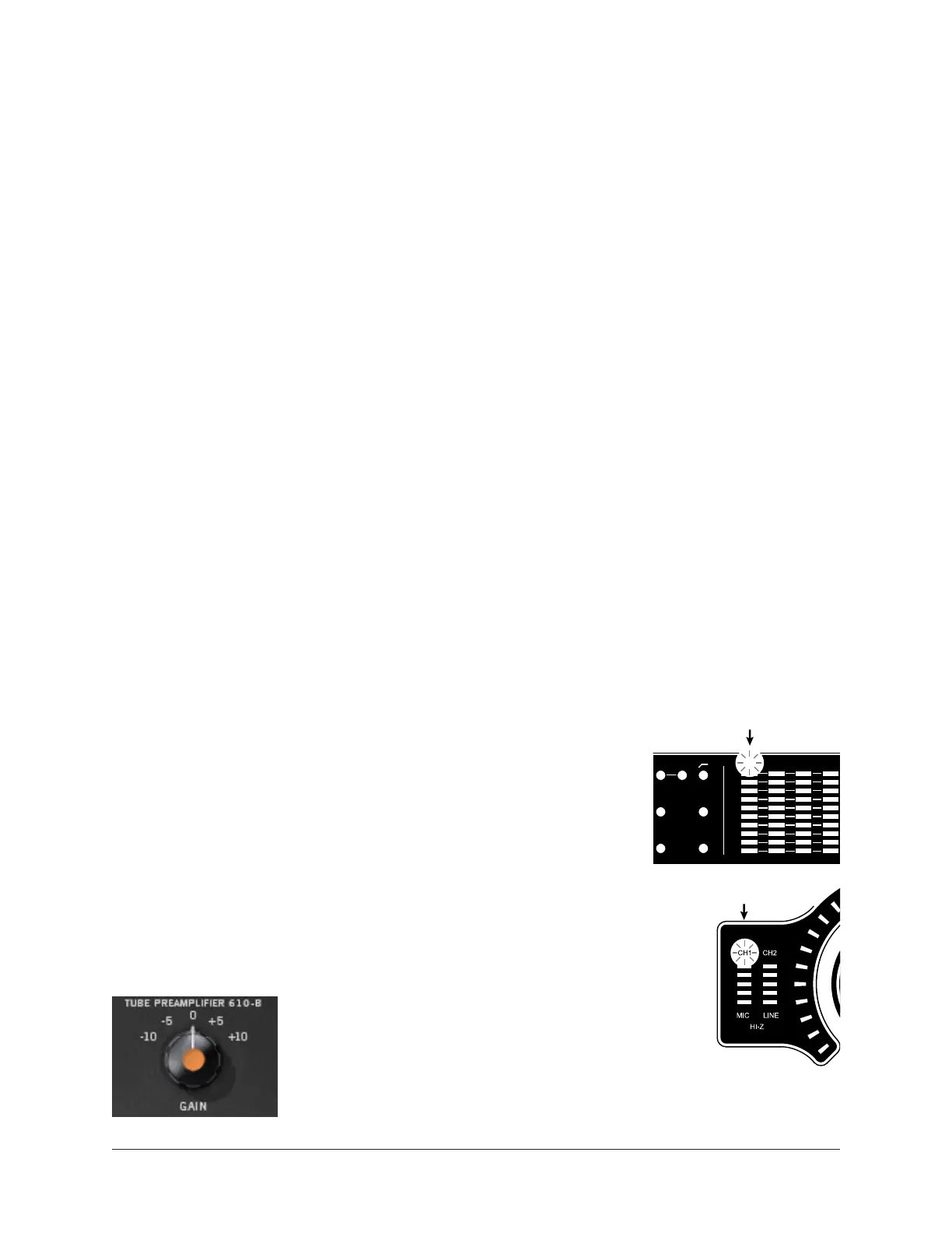
Gain Stage Mode – Apollo Panel Indication
Apollo’s panel channel selection indicator LED flashes when
Gain Stage Mode is active for the currently selected preamp
channel. The indication varies with the specific Apollo model:
Apollo, Apollo 8, Apollo 8p
The channel selection number LED above its input meter
flashes when Gain Stage Mode is active, as shown at right.
Apollo Twin
The channel selection number LED (CH1 or CH2) above the
input meters flashes when Gain Stage Mode is active, as
shown at right.
Gain Stage Mode – Unison Plug-In Indication
A colored dot appears within the
Unison plug-in interface on the target
parameter being controlled, as shown at
left.
See Gain Stage Colors for related information.
MIC
+48
Ø LINK
1 2
3 4
PAD
LINE
EXT
CLOCK
UAD
LINK
PAD
MIC/LINE
+48V
Ø LINK
CLIP
0
-6
-3
-9
-12
-15
-18
-21
-27
CLIP
0
-6
-3
-9
-12
-15
-18
-21
-27
Apollo Twin
Flashing Channel Selection
Apollo (rack models)
Flashing Channel Selection
2 3 41
INT
CLOCK
MIC
+48
Ø LINK
1 2 1 23 4 5 6 7 8
PAD
LINE
EXT
CLOCK
UAD
LINK
PAD
MIC/LINE
+48V
Ø LINK
CLIP
0
-6
-3
-9
-12
-15
-18
-21
-27
CLIP
0
-6
-3
-9
-12
-15
-18
-21
-27
Apollo Twin
Flashing Channel Selection
Apollo (rack models)
Flashing Channel Selection
2 3 41