To install an RF amplifier tray:
1.
If you are going to test the configured NC4000, make the applicable RF and power
connections to the base housing (ports P1 through P6) before installing the RF amplifier.
Ensure that all six seizure nuts are torqued to 6.25 foot-pounds (8.5 newton-meters). See
4.4 RF Coaxial Cable Connections on page 4-6 through 4.6 Fiber Optic Cable Connections on
page 4-8 for cable connections in the field.
2.
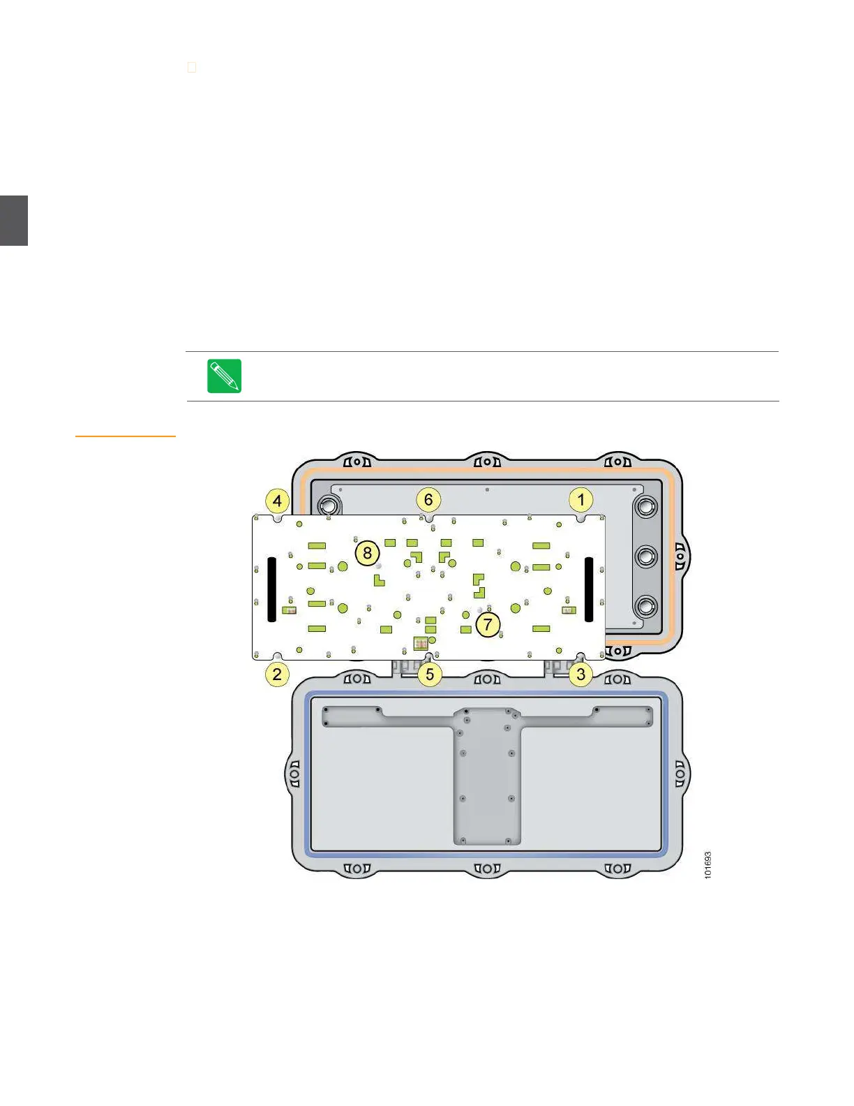
Orient the RF amplifier tray so that port P1 (upper right corner) lines up with port P1 in the
base (Figure 3.1). Gently push the RF amplifier into the base until it’s firmly seated.
3.
Using a nut driver, start all eight screws, then torque the screws to 15 inch-pounds (1.69
newton-meters) in the sequence shown in (the correct sequence is also marked on the
cover tray). Re-torque screws 1 through 8 a second time to compensate for any flexing of
the RF amplifier tray. (You can use a screwdriver or nut driver.)
4.
You must remove/replace the RF amplifier tray to connect/disconnect cables to/from
connectors P1 through P6. See 4.3 Removing and Replacing the RF Amplifier Tray on page 4-5
for detailed instructions on removing and replacing the RF amplifier in the field.
Note
Always tighten the screws holding the RF amplifier tray in the order shown in
Figure 3.1 (the correct sequence is also marked on the cover tray). Failure to follow
this sequence can result in warping and misalignment.
Figure 3.1
Installing an RF
Amplifier Tray