Copyright © 2016 ASIX Electronics Corporation. All rights reserved.
AX99100
PCIe to Multi I/O Controller
Offset 0x00~0x16:
Please reference section 3.3.1.
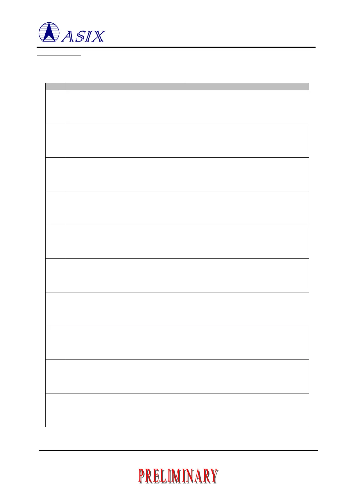
Local Bus Interrupt Enable/Miscellaneous Setting (0x19~0x18)
INT0 Wakeup Enable
1: Enable INT0 wakeup
0: Disable INT0 wakeup
Hardware Default Value: 0x0
INT1 Wakeup Enable
1: Enable INT1 wakeup
0: Disable INT1 wakeup
Hardware Default Value: 0x0
RDY Timeout Enable
1: Enables RDY timeout.
0: Disable RDY timeout.
Hardware Default Value: 0x0
RDY Timeout Select
1: 128 clocks
0: 32 clocks
Hardware Default Value: 0x0
Ready Polarity
1: Active high
0: Active low
Hardware Default Value: 0x1
ALE Polarity
1: Active High
0: Active Low
Hardware Default Value: 0x1
Synchronous Bus
1: Synchronous Bus
0: Asynchronous Bus
Hardware Default Value: 0x0
Multiplexed Bus
1: Address and Data multiplexed
0: Address and Data bus separated
Hardware Default Value: 0x0
CLKO Driven Strength
1: 8mA
0: 4mA
Hardware Default Value: 0x1
CLKO Output Enable
1: Enable clock output
0: Disable clock output
Hardware Default Value: 0x1
 Loading...
