Do you have a question about the Assa Abloy Effeff 519 and is the answer not in the manual?
General information, features, versions, and functions of the motorised multi-point lock 519.
Explanation of the self-locking mechanism and integration into access control.
Suitability for barrier-free doors with swing door drives.
Enables continuous unlocking for access in public buildings.
Details the specific version of the motorised multi-point lock 519.
Explains the E-function for manual unlocking from outside.
Describes the two lock versions based on door handing (DIN left/right).
Information on the purpose and target audience of the manual.
Explanation of danger, warning, caution, attention, and note symbols used.
Crucial safety warnings regarding fire protection, device damage, and operation.
Important notices for conformity with escape and panic door standards.
Specifies suitable applications and limitations for the lock.
Defines key terms and components used in the manual.
Details the classification key for DIN EN 1125 panic door locks.
Shows the CE marking and associated certifications.
Details the classification key for DIN EN 179 emergency exit door locks.
Describes the mechanical automatic locking function of the lock.
Explains how the lock engages and locks using its components.
Troubleshooting steps for when the striking plate sensor fails to recognize the plate.
Situations where the motorized multi-point lock is unlocked.
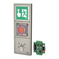
Integration of the lock with electronic access control systems.
Enables permanent unlocking via a permanent contact.
Switches between permanent unlocking and locking.
Monitors door status and reacts to the striking plate.
Illustrates application scenarios like barrier-free and fire/smoke protection doors.
Secure locking for fire/smoke doors with fire alarm systems.
Crucial safety warnings regarding damage and specifications for installation.
Notes on property damage from work on the door leaf.
Instructions for preparing and cleaning the lock pocket before mounting.
Steps for connecting cables for power and control unit.
Procedure for fastening the lock and fittings into the door.
Procedure for installing the striking plate in the door frame.
Steps for installing fittings and the locking cylinder.
Testing the lock for proper operation after installation.
Routing cables and connecting the lock.
Wiring diagram for connecting without an additional control unit.
Connection diagram and configuration for the Ull control module.
Details control inputs like door contact, fire alarm, and unlocking.
Explains DIP switches and cover contact settings for the Ull module.
Configuration options for the rotary switch S2.
Configuration settings for DIP switches 1-4.
How to query status messages and control external devices via the Ull module.
How to connect the fire protection module to the UII module.
Using the fire protection module for fire doors.
Warning about missing wire jumpers for the fire protection module.
Guidelines for selecting and positioning locking cylinders.
Reworking profile slugs for level sliding surfaces.
Specifications for producing custom striking plates.
Expanding the 3-way system to a 4-way system for tall doors.
Using spacer plates to reduce rebate gap or prevent jamming.
Adjusting follower/cylinder position when using spacer plates.
How spacer plates prevent jamming in wooden doors.
Detailed technical specifications of the lock.
Electrical data and relay output capacities for the Ull module.
Various types of striking plates available for the lock.
Details on the additional bolt accessory for high doors.
Spacer plate sets for specific applications.
Flexible lead covers for cable guidance.
Panic bars for model 519E in accordance with DIN EN 1125.
Power supply, cable, UII module, and fire protection module.
Instructions for maintenance and important warnings.
Information on statutory warranty periods.
Guidelines for recycling packaging and product disposal.
Troubleshooting issues when the lock fails to unlock.
Troubleshooting issues when the lock fails to lock.
Dimensions for Euro-profile cylinders.
Dimensions for Swiss profile cylinders.
Dimensions of the striking plate.
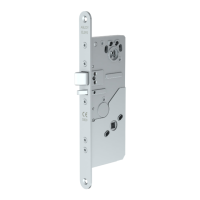
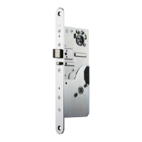
Dimensions of the lock mechanism.
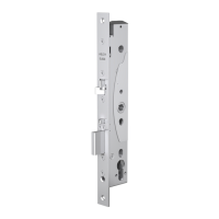
Dimensions for the electric multi-point lock with latch lock.
Dimensions of striking plate with integrated escape door strike.
Dimensions of the 3-piece striking plate.
| Brand | Assa Abloy |
|---|---|
| Model | Effeff 519 |
| Category | Locks |
| Language | English |