64
EN
Installation
Configuration of the UII control module / meaning of the switches
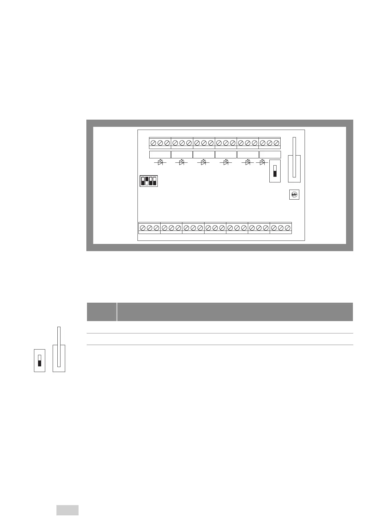
Pic. 9 :
Switches for configura-
tion of the UII control
module
16 17 18 19 20 21 22 23 24 25 26 27 28 29 30 31 32 33
b4c132b5c68791110 12 1413 15 cb
4132
S2
7
6
5
4
3
2
1
0
F
E
D
C
B
A
9
8
LD 1 LD 2 LD 3 LD 4 LD 5 LD 6
ON
1
S3
S1
DIP
Cover contact (S1) and single-pole DIP switch (S3)
The cover contact (S1, “flat spring”) is designed as a sabotage message, if someone removes the cover
without authorisation. This precludes electrical triggering by means of the triggering control input. The
“Fault alarm” relay (on LD 6, cf Tab. 6, page 65) is activated.
Switch
position
Description
ON Cover contact is bypassed and inactive.
1 Cover contact is active.
Tab. 4:
Cover contact / sabotage
message
ON
1
S3
S1
 Loading...