16
ASSA ABLOY Hospitality
66 8003 016-3
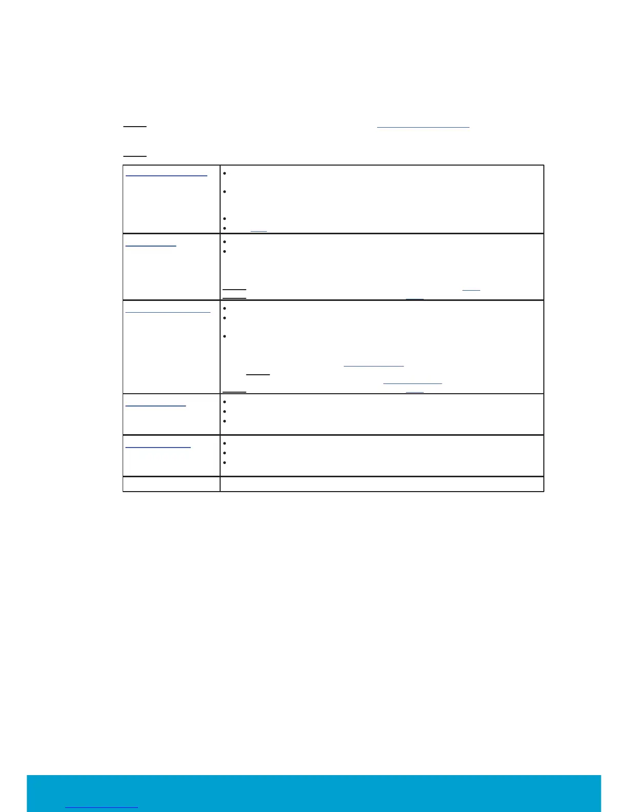
3.1.4.2 High voltage terminal block (8 pole; 5.0mm spacing)
Note: The parameters are set up in Visionline; see the section To set up a thermostat profile for details.
Note:
For connection examples, click the links in the left column of Table 2 below.
Mains voltage input
Universal voltage input 100VAC-277VAC; 50/60Hz;
rated impulse voltage 4kV
This is the voltage that is output on the high voltage terminals,
but it is also used as power supply input for the thermostat
internal circuits
N = Neutral
L = Live
Fan outputs
Type 1.B action. Max load 3A (3FLA/18LRA)
Mains voltage output at
- G1: Fan 1, when the fan is to be run at lowest speed
- G2: Fan 2, when the fan is to be run at medium speed
- G3: Fan 3, when the fan is to be run at high speed
Note:
For information about fan settings in Visionline, click here.
Note:
For information about live output, click here.
RV: Reversing valve
Type 1 action. Max load 0.5A
Primary function: Used for switching between summer/winter
(cold/hot water in the pipes of a 2-pipe system)
Alternative functions (must be set up in Visionline):
- Mains voltage output when the room is occupied
- Mains voltage output when the guest enters the
room for the first time; welcome scene
Note: These alternative functions can also be set up for G2.
- Can be used as return (close) for floating valves
Note: For information about live output, click here.
Y: Cool output
Type 1 action. Max load 0.5A
Mains output for cool actuator
Primary function: Mains voltage output when the temperature
is above the set temperature (plus deadband)
W: Heat output
Type 1 action. Max load 0.5A
Mains output for heat actuator
Primary function: Mains voltage output when the temperature
is below the set temperature (minus deadband)
Table 2
 Loading...