Chapter 2 PARTS AND THEIR FUNCTIONS
7
Table 2.2 Names of rear panel parts
No. Part Description of function
1 Power socket (*1) Cannon connector, DC power input socket (GND: pin 1; DC IN: pin 4).
2 SDI IN Ach HD-SDI signal input connector.
3 SDI IN Bch HD-SDI signal input connector.
4 Y IN
HD analog Y signal input connector
Synchronization is provided using the Y signal in the case of analog inputs.
5 Pb IN HD analog Pb (Cb) signal input connector
6 Pr IN HD analog Pr (Cr) signal input connector
7 MONITOR OUT
Output connector for simplified monitoring of SDI input signals.
SDI A images are output when the SDI A input is selected.
SDI B images are output when the SDI B input is selected.
SDI A images are output when the analog input or composite input is selected.
8 COMPOSITE IN Composite signal input connector
When composite signals are input, the waveforms, etc. displayed are the waveforms,
etc. obtained after the signals have been converted into component signals.
In regard to PAL signals, however, the waveforms of the 3 lines each at the start and
end of the video signals will be more disturbed than in actuality.
9 TALLY connector (*2) D-sub 9pin (female)
10 REF IN
Reference input connector (HD tri-level sync, BB_525, BB_625), terminated with a
75Ω resistance.
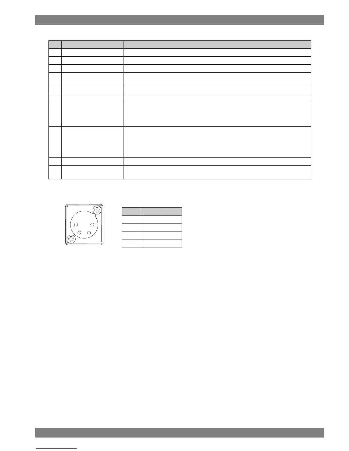
*1: Power socket (no.1 in rear panel view)
Pin No. Function
1 GND
2 NC
3 NC
4 DC IN (10-18V)
4
3 2
1

 Loading...