8
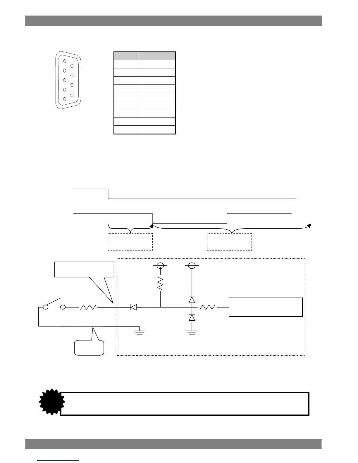
*2: TALLY connector (no.9 in rear panel view)
Pin No. Function
1 GND
2 TALLY 2(G)
3 PRESET 1
4 PRESET 2
5 GND
6 PRESET 3
7 TALLY 1(R)
8 PRESET 4
9 PRESET 5
When GND and pin 2 are shorted, the green tally lamp lights; when GND and pin 7 are shorted, the red tally lamp lights.
Details on the PRESET pins are provided below. Any of these pins become operational when they are shorted with
GND.
Their functions are established by setting the pins from high to low (MAKE) (edge operation). (The switch pressed last
has priority.)
* Design the circuitry in such a way that the cable resistance is 50Ω or less.
1
5
6
9
PRESET 1
data is read out
PRESET 2
data is read out
PRESET 1
PRESET 2
Do not plug a cable into or unplug one from the TALLY connector while the power is supplied to the
monitor.
CAUTION
Remote connector reception area
DM monito

 Loading...