Rubber Track Loader
5. Operator Enclosure Disassembly and Assembly
5-2
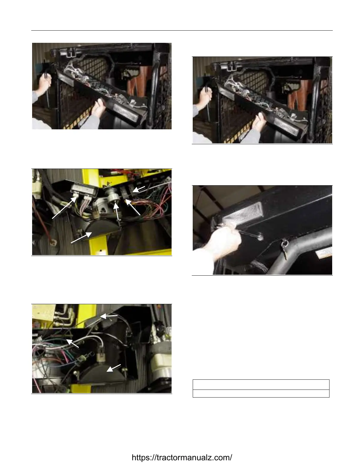
Figure 5-2 5-002
2. Carefully lower the light bar with the wire har-
ness attached.
Figure 5-3 5-003
3. View of light bar interior (to operator’s right when
seated). Interior components are now accessible
for servicing.
Figure 5-4 5-004
4. View of light bar interior (to operator’s left when
seated).
Light Bar Installation
Figure 5-5 5-005
1. Carefully position the light bar, without pinching
the wiring harness against the cab frame.
Figure 5-6 5-006
2. Secure the light bar to the cab frame with the
two bolts.
Ignition Switch Removal and
Installation
The tools required for ignition switch removal and
installation are listed in Table 5-2. Use manufac-
turer-recommended tools whenever possible.
Table 5-2
Required Tools
Combination Wrench
Ignition Switch Removal
1. Lower the light bar. Refer to Chapter 5. Light Bar
Removal procedure.
Headlight
Ignition
Switch
Console
Gauge
Aux. Hyd.
Switch
Light
Switch
Headlight
Dome
Light
Level
Gauge
https://tractormanualz.com/
 Loading...