Rubber Track Loader
8. Hydraulic Reservoir Disassembly and Assembly
8-3
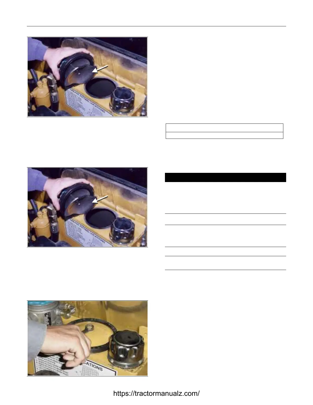
Clamping
Disk
Figure 8-4 8-013
2. Remove the access cover assembly from the
reservoir.
Access Cover Assembly Installation
Clamping
Disk
Figure 8-5 8-013
1. Insert the access cover assembly with the
clamping disk extending completely through the
opening in the top of the reservoir and into the
tank.
Figure 8-6 8-012
2. Tighten the access cover bolt.
Reservoir Gauge Removal and
Installation
The tools required for reservoir gauge removal and
installation are listed in Table 8-3. Use
manufacturer-recommended tools whenever
possible.
Table 8-3
Required Tools
Combination Wrench
Reservoir Gauge Removal
! WARNING !
Hot oil can cause personal injury. Make sure the oil is
cool before removing any components or lines.
Remove the oil filler cap only when the engine is
stopped and the filler cap is cool enough to touch with
your bare hand.
NOTICE
Collect and contain liquids in a suitable container. Dispose
of all liquids according to local regulations and mandates.
Note: During disassembly, cap all hoses and fittings to
prevent fluid loss and contamination of the system fluids.
1. Drain the hydraulic fluid. Refer to Chapter 14.
Maintenance.
2. Remove the filter manifold. Refer to Chapter 8.
Filter Assembly Removal.
https://tractormanualz.com/
 Loading...