Both arrows on AT504A, AT503A and AT502V used the 6
th
and 5
th
digit of the 7-segment
LED display to control. In order to let arrows show brightly, sending “8” to 6
th
and 5
th
digit will be the good choice.
Data [0] : “8:” -> light on up arrow (AT504A and AT503A), right arrow (AT502V)
Data [1] : “8” -> light on down arrow(AT504A and AT503A), left arrow(AT502V)
Data [2] ~ Data [5] : The display message for AT504A, AT503A and AT502V.
Data [6] : dot position.
AT503A/AT502V has two message buffers to display, one related feature for the return
message is to inform user the buffer is full.
Buffer full: The maximum display buffer size for AT503A and AT502V is 2 records. When
the buffer is full and still send 3rd data to it, then the original first data will be
dropped out automatically and meanwhile AT503A or AT502V will send one
message back to inform this situation.
Sub-command = 64H , please refer 4.4.10.
Data(0) = 02H , Mean the AT503A or AT502V’s buffer is full
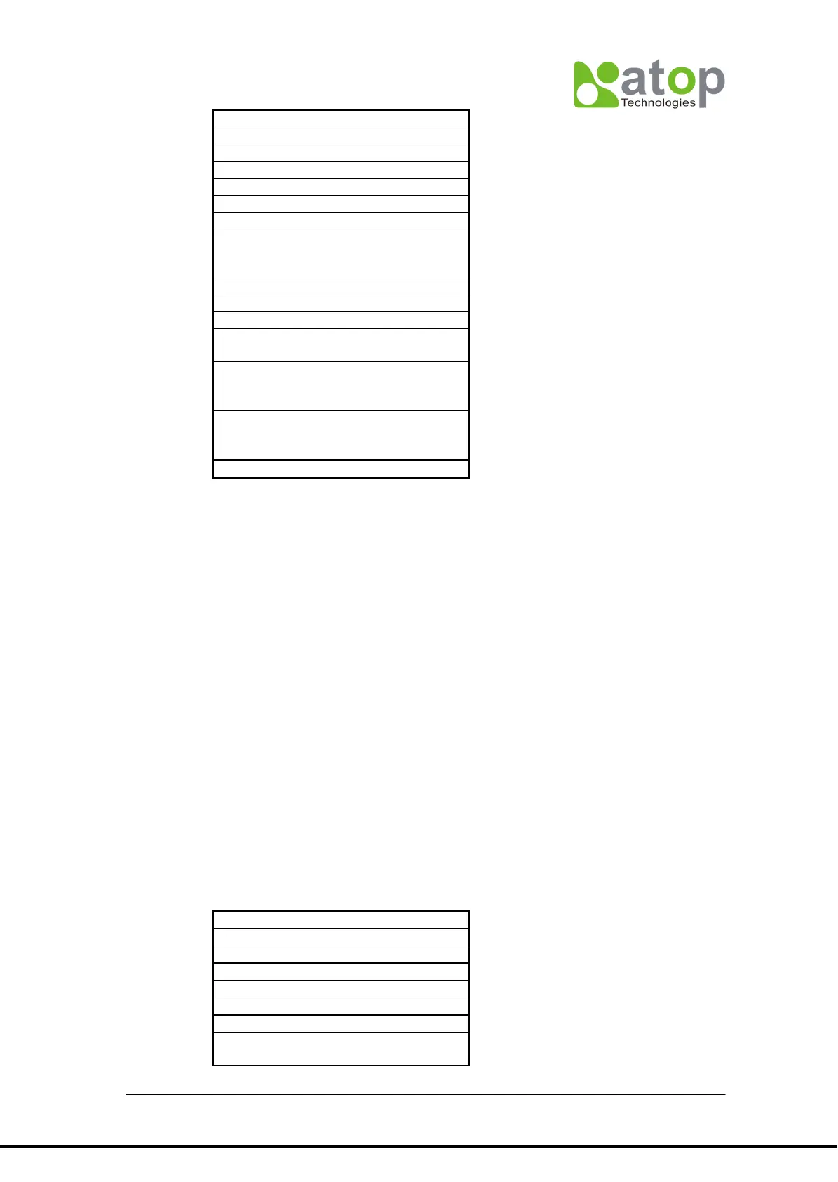
4.5.3 Protocol for AT506-3W-123
The CCB(communication Control Block ) from Host PC to AT506-3W-123.
CCB Description