Protected by copyright. Copying for private or commercial purposes, in part or in whole, is not
permitted unless authorised by AUDI AG. AUDI AG does not guarantee or accept any liability
with respect to the correctness of information in this document. Copyright by AUDI AG.
◆ When working with the fault reader, no adapter cable from test box V.A.G 1598 may be connected to op‐
erating and display unit -E87.
Required measuring and testing equipment:
- -> Test box V.A.G 1598 and the pertinent adapter cables V.A.G 1598/11 and V.A.G 1598/12.
- Handheld multimeter V.A.G 1526,
- Adapter set V.A.G 1594,
- Diode test lamp V.A.G 1527,
- Temperature sensor with appropriate tester,
Test requirements
All fuses OK in line with current flow diagram.
Connect test box adapter cables V.A.G 1598/11 and 12 to connector for operating and display unit -E87
- Switch off ignition.
- Remove operating and display unit -E87 (=>Page 174 ).
- -> Connect adapter cables V.A.G 1598/11 and 12 to the vehicle wiring harness connectors.
Notes:
◆ Do not connect operating and display unit -E87.
◆ For measurement purposes, connect test box V.A.G 1598 to the respective adapter cable.
◆ On adapter cable V.A.G 1598/12, the socket assignment is identical to the pin assignment of operating and
display unit -E87.
◆ On adapter cable V.A.G 1598/11, the socket assignment is not identical to the pin assignment of operating
and display unit -E87.
=>Pin assignment, Page 47 .
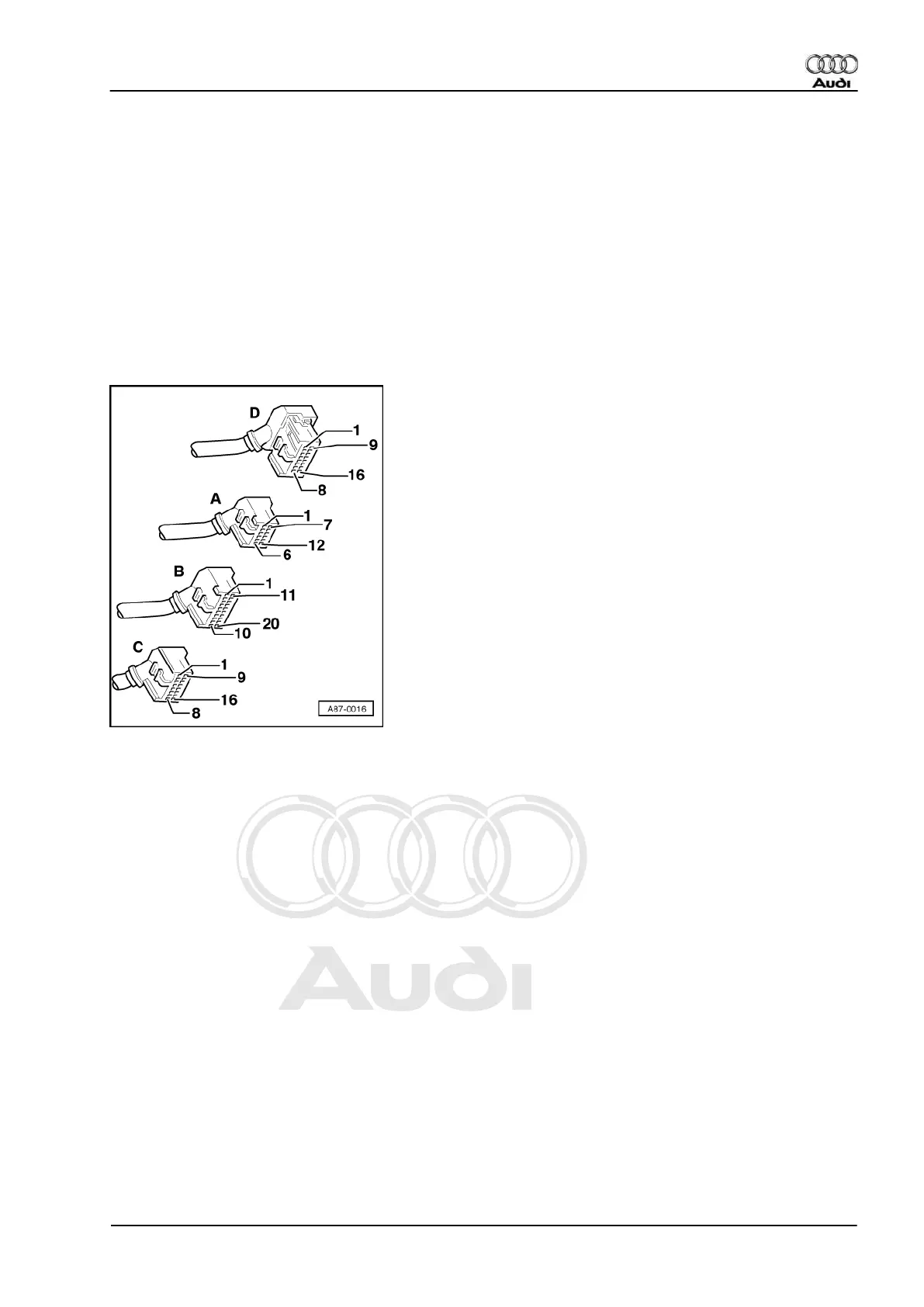
Pin assignment of test box V.A.G 1598 with adapter cable V.A.G 1598/11
Notes:
◆ With adapter cable V.A.G 1598/11, the contact assignment of connectors A and B is not identical to the
socket assignment on the test box.
◆ The pin assignment of connector C in adapter cable V.A.G 1598/11 is not identical to those of the sockets
on the test box.
◆ The pin assignment of connector D in adapter cable V.A.G 1598/12 is identical to those of the sockets on
the test box.
◆ Due to the use of two adapter cables for the connectors for operating and display unit -E87 (V.A.G 1598/11
and 12), no earth connection is possible when adapter cable V.A.G 1598/11 is connected. To perform the
Electrical checks, it is therefore necessary in various test steps to take measurements against a suitable
Audi A3 1997 ➤
Heating, Air Conditioner - Edition 06.2000
10.2 - Electrical check on operating and display unit -E87 47