Protected by copyright. Copying for private or commercial purposes, in part or in whole, is not
permitted unless authorised by AUDI AG. AUDI AG does not guarantee or accept any liability
with respect to the correctness of information in this document. Copyright by AUDI AG.
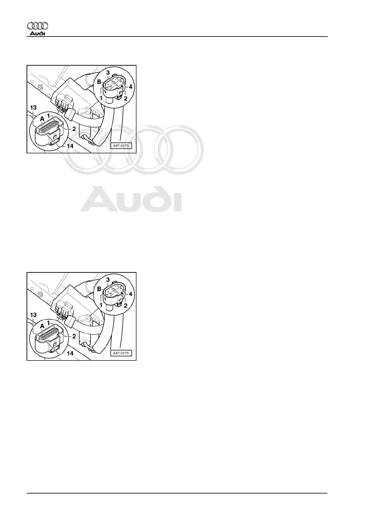
11.3 - Electrical check at control unit -J293 (version for High-pressure sensor -G65)
-> Pin assignment for radiator fan control unit -J293
• Location:
on left longitudinal member in engine compartment
• Function:
- Switches radiator fans -V7 to 1st and 2nd speed
- Actuates AC magnetic clutch -N25.
- Processes the square-wave signal of high-pressure sensor -G65 and, if the refrigerant circuit pressure
is OK, sends a positive signal to -E87.
- Switches on pump for refrigerant supply -V51 (in vehicles with pump for refrigerant supply -V51) when
the ignition is switched on. The pump remains in operation for a brief time after the ignition is switched
off.
=> Relevant Workshop Manual Injection and Ignition system
Notes:
◆ -> The following contacts in connector -A- to control unit -J293 are vacant:
- Contact 1 (in vehicles without pump for refrigerant supply -V51)
- Contact 3
- Contact 11 (at the moment only in vehicles with petrol engines with map-controlled engine cooling and
in vehicles with 81 KW diesel engine).
- Contacts 5 and 14 (dependent on type of -J293 there can be a bridge between these two contacts).
=> Current Flow Diagrams, Electrical Fault-Finding and Fitting Locations
- Contact 13 (reserved for compressor switch-off by dash panel insert, only occupied in individual vehicles).
=> Current Flow Diagrams, Electrical Fault-Finding and Fitting Locations
◆ Radiator fan control unit -J293 versions and vehicle wiring differ for vehicles with pressure switch -F129 and
high-pressure sensor -G65.
Audi A3 1997 ➤
Heating, Air Conditioner - Edition 06.2000
76 01 - Self-diagnosis, Electrical check