Protected by copyright. Copying for private or commercial purposes, in part or in whole, is not
permitted unless authorised by AUDI AG. AUDI AG does not guarantee or accept any liability
with respect to the correctness of information in this document. Copyright by AUDI AG.
=> Parts List
=> Current Flow Diagrams, Electrical Fault-Finding and Fitting Locations
◆ Control unit -J293, installed in vehicles with high-pressure sensor -G65, is available in 2 designs.
- In design "1" the radiator fan is automatically switched on in conjunction with the compressor (the first
fan speed is activated regardless of the pressure in the refrigerant circuit).
- In design "2" the compressor is switched on without the radiator fan; the first fan speed is only activated
once the pressure in the refrigerant circuit has exceeded 12 bar.
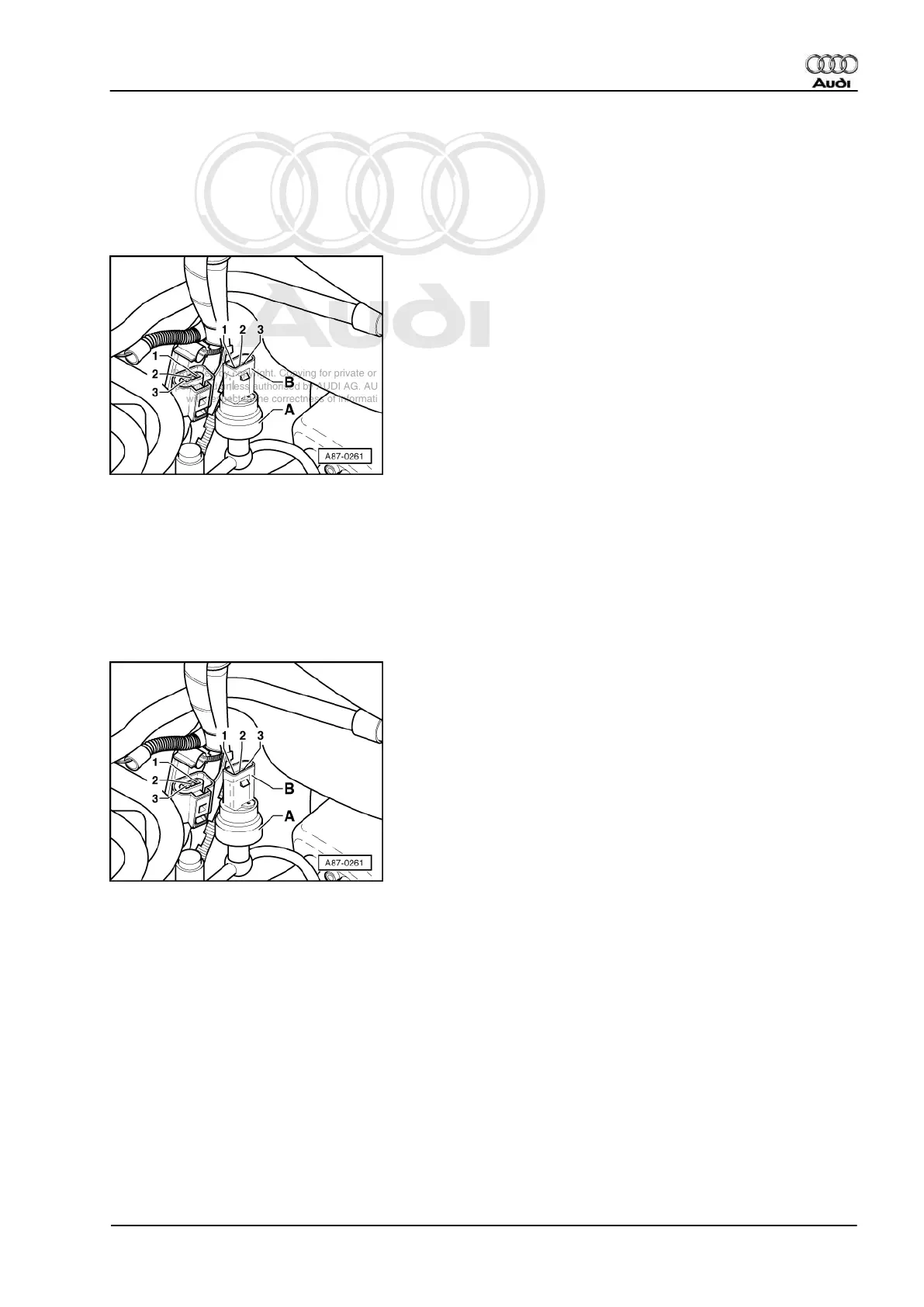
-> Pin assignment for high-pressure sensor -G65
Contact 1, earth
Contact 2, signal output (square-wave signal to -J293 and to engine control unit)
Contact 3, positive (terminal 15)
Notes:
◆ -> The compressor will not be switched on if connector -B- is disconnected.
◆ High-pressure sensor -A- is an electronic control unit that generates a square-wave signal whose duty cycle
changes with refrigerant circuit pressure =>Page 85 .
Pin assignment at refrigerant temperature switch -F18 / -F54
Switch -F54 (between contact 1 and 2 closes at approx. 95 °C - the radiator fans are switched to 1st speed).
Switch -F18 (between contact 3 and 2 closes at approx. 102 °C - the radiator fans are switched to 2nd speed).
Audi A3 1997 ➤
Heating, Air Conditioner - Edition 06.2000
11.3 - Electrical check at control unit -J293 (version for High-pressure sensor -G65) 77