Protected by copyright. Copying for private or commercial purposes, in part or in whole, is not
permitted unless authorised by AUDI AG. AUDI AG does not guarantee or accept any liability
with respect to the correctness of information in this document. Copyright by AUDI AG.
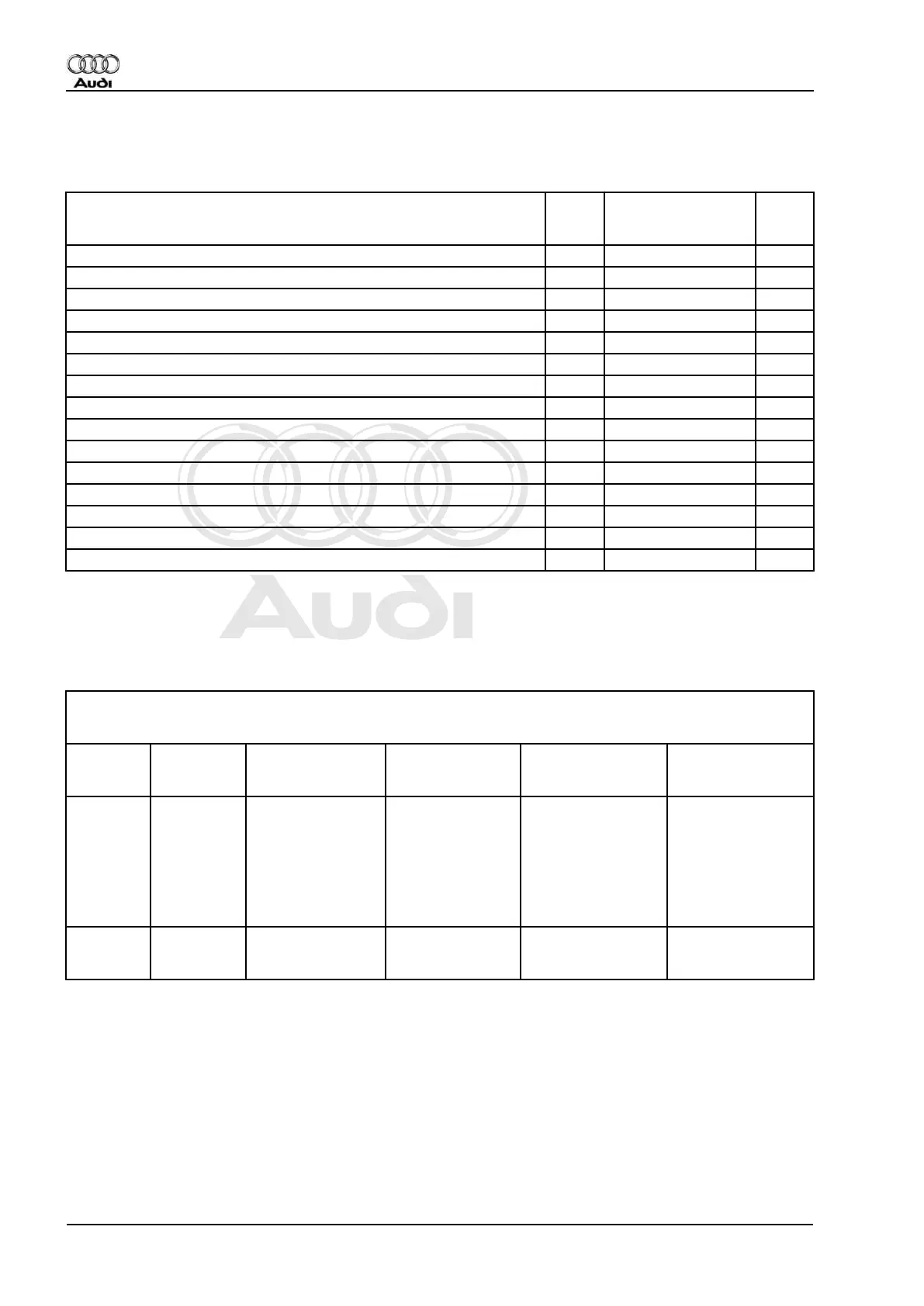
Ambient temperature-dependent resistance of temperature sensors/senders in kω(kilo-ohms)
At sensor/sender installation location, temperature measured in °C
(degrees Celsius)
Sender
-G192
Temperature sensor
-G17
-G89
Sender
-G191
-30 (52.7) 18.1 -
-20 (28.6) 9.95 -
-10 16.2 5.59 (47)
0 9.40 3.28 (29)
5 7.27 2.54 (23)
10 5.66 1.99 18.5
15 4.45 1.57 15
20 3.50 1.25 12.2
25 2.79 1.00 10.0
30 2.23 0.80 8.3
35 1.80 0.65 6.8
40 1.45 0.53 5.7
50 0.97 0.36 4.1
60 0.67 0.25 2.9
70 0.47 - 2.2
Test step 3
Fresh air blower -V2 and relevant control unit -J216
Select measuring range on hand-held multimeter V.A.G 1526:
Voltage measurement (20V =)
- Adapter cable V.A.G 1598/11 connected
Test step V.A.G 1598
socket
Testing of ▪ Test conditions
- Additional opera‐
tions
Specified value Remedies if speci‐
fied value not at‐
tained
3.1 16
and
earth
Control unit -J126 ▪ Ignition on. - Voltage less than 5
V.
Fresh air blower not
running.
- Use current flow di‐
agram to locate and
eliminate short to
positive in the wiring
between -J126 and -
E87.
Replace control unit
-J126.
3.2 4
and
earth
Power supply for
fresh air blower -V2
▪ Ignition on. - approx. battery
voltage
- Use current flow di‐
agram to repair pow‐
er supply.
Note:
Earth applied e.g. to connector D contact 14.
Audi A3 1997 ➤
Heating, Air Conditioner - Edition 06.2000
64 01 - Self-diagnosis, Electrical check