Part names and functions
9
LINK OUT port
When linking multiple receivers, connect the included link cable to this port.
DC input jack
Connect the included AC adapter.
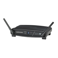
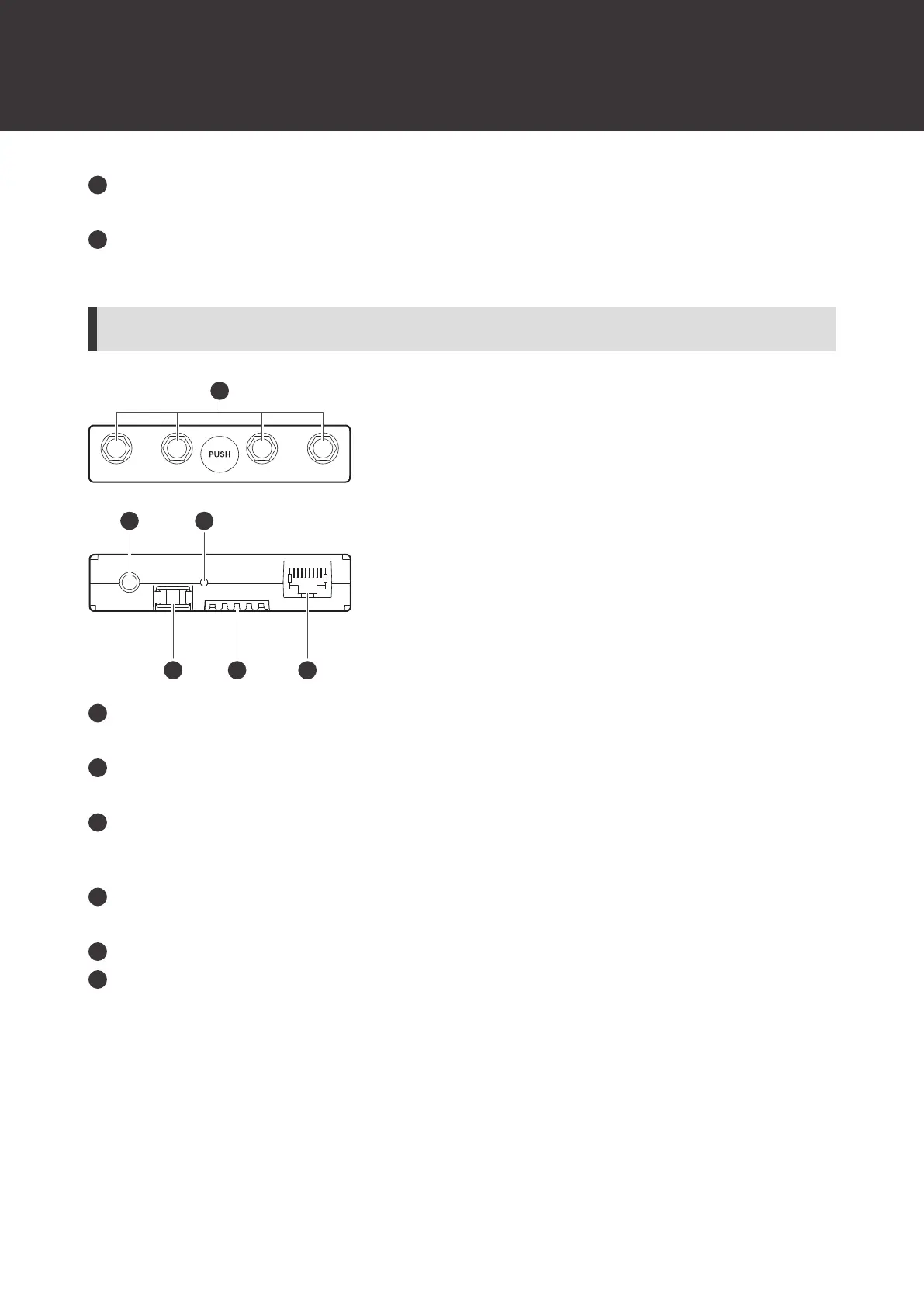
ATW-RU14
Antenna connector
Attach an included antenna.
Camera thread (1/4-inch)
Use this thread to secure the receiver unit when installing it externally.
Indicator lamp
Lights when the device is on. This lamp also shows the status of this receiver unit. Refer to "Indicator lamps" (p. 73)
for details.
Latch module
This fixing module is used when the receiver unit is stored in the receiver chassis.
Internal connection terminal
External connection port
When externally installing the receiver unit, connect the LAN cable (Cat.5e or higher) from the receiver chassis to
this port.