5.3.1. Overview on coupling variants
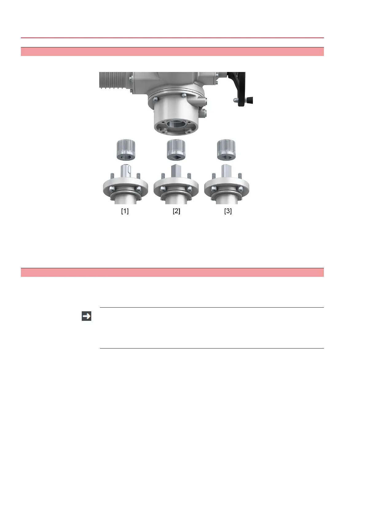
Design Figure 12:Valve attachment via coupling
[1] Bore with keyway
[2] Square bore
[3] Bore with two-flats
Application
●
For valve attachments according to EN ISO 5211
●
For rotating, non-rising valve stem
5.3.2. Actuator (with coupling): mount
Unbored couplings or couplings with pilot bore must be machined to match the valve
shaft prior to mounting the actuator to the valve (e.g. with bore and keyway, two-flat
or square bore).
Assemble valve and actuator in the same end position. As standard, the actu-
ator is supplied in end position CLOSED.
→
Recommended mounting position for butterfly valves: End position CLOSED.
→
Recommended mounting position for ball valves: End position OPEN.
Assembly steps
1. If required, move actuator in same end position as valve using the handwheel.
2. Clean mounting faces, thoroughly degrease uncoated mounting surfaces.
3. Apply a small quantity of grease to the valve shaft [2].
16
SQV 05.2 – SQV 14.2 / SQRV 05.2 – SQRV 14.2 Control unit: electronic (MWG)
Assembly ACV 01.2 Non-Intrusive Profinet

 Loading...


