6.2.1. Terminal compartment (for mains connection): open
Figure 20: Open mains terminal compartment
[1] Connection housing
[2] Screws for frame
[3] O-ring
[4] Screws for socket carrier
[5] Socket carrier
[6] Cable entries for mains connection (power and control contacts)
[7] Blanking plug
[8] Cable gland (not included in delivery)
Electric shock due to presence of hazardous voltage!
Failure to observe this warning results in death or serious injury.
→
Disconnect device from the mains before opening.
→
Wait for 30 seconds after power cut-off prior to opening the housing.
1. Loosen screws [2] and remove connection housing [1].
2. Loosen screws [4] and remove socket carrier [5] from connection housing [1].
3. Insert cable glands [8] suitable for connecting cables.
➥
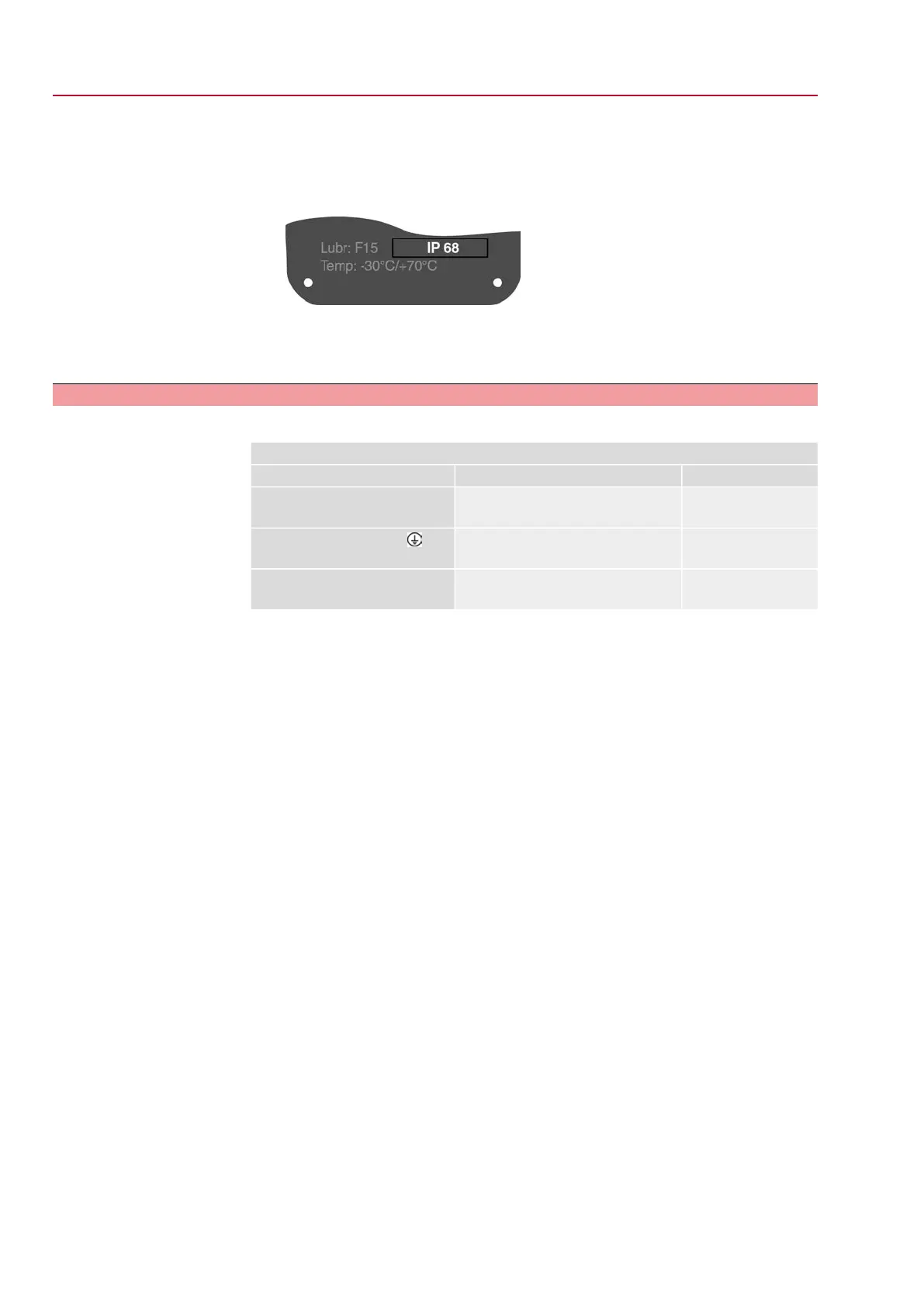
The enclosure protection IP… stated on the name plate is only ensured if suit-
able cable glands are used.
Figure 21: Example: Name plate for enclosure protection IP68
4. Seal unused cable entries [6] with suitable blanking plugs [7].
Information
Fieldbus connection can be accessed separately from the mains connection (refer
to <Fieldbus terminal compartment: open>.
24
SQV 05.2 – SQV 14.2 / SQRV 05.2 – SQRV 14.2 Control unit: electronic (MWG)
Electrical connection ACV 01.2 Non-Intrusive Profinet

 Loading...


