6. Electrical connection
6.1. Basic information
Electric shock due to presence of hazardous voltage!
Failure to observe this warning can result in death, serious injury, or property damage.
→
The electrical connection must be carried out exclusively by suitably qualified
personnel.
→
Prior to connection, observe basic information contained in this chapter.
→
After connection but prior to applying the voltage, observe the <Commissioning>
and <Test run> chapters.
Risk of overheating during operation with mounted transport protection!
→
Prior to connection, remove transport protection from cooling fins.
Figure 17: Remove transport protection
Wiring diagram/terminal
plan
The pertaining wiring diagram/terminal plan (in German or English) is attached to
the device in a weather-proof bag, together with these operation instructions. It can
also be requested from AUMA (state order number, refer to name plate) or
downloaded directly from the Internet (http://www.auma.com).
Permissible networks
(supply networks)
The actuators are suitable for use in TN and TT networks with directly grounded star
point for nominal voltages up to maximum 480 V AC. Use in IT network is permissible
for nominal voltages up to maximum 480 V AC. For IT network, a suitable, approved
insulation monitor measuring the pulse code is required.
Current type, mains
voltage, mains fre-
quency
Type of current, mains voltage and mains frequency must match the data on the
actuator controls and motor name plates. Also refer to chapter <Identification>/<Name
plate>.
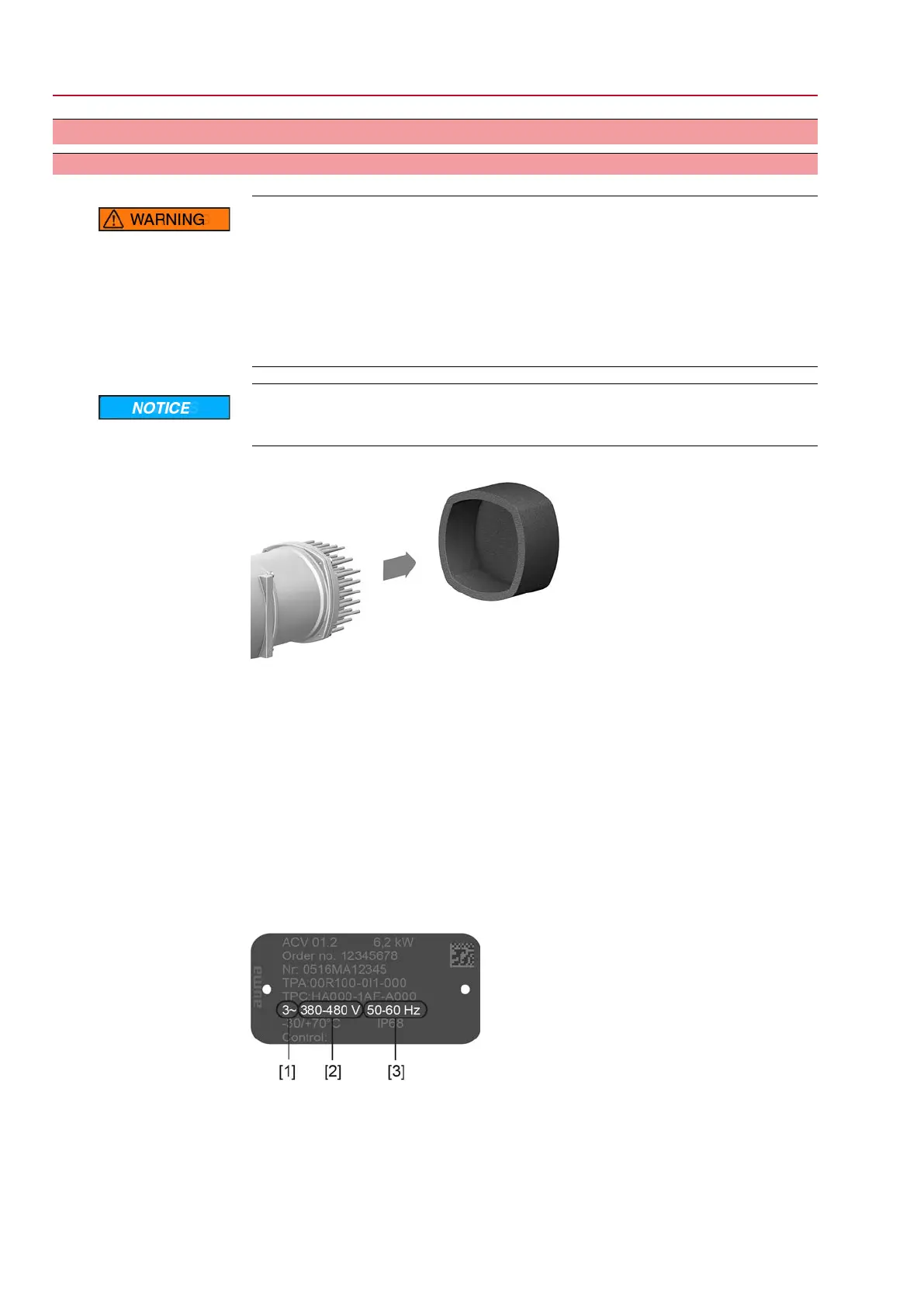
Figure 18: Actuator controls name plate (example)
[1] Type of current
[2] Mains voltage (voltage range)
[3] Mains frequency (frequency range)
Protection and sizing on
site
For short-circuit protection and for disconnecting the actuator from the mains, fuses
and disconnect switches have to be provided by the customer.
20
SQV 05.2 – SQV 14.2 / SQRV 05.2 – SQRV 14.2 Control unit: electronic (MWG)
Electrical connection ACV 01.2 Non-Intrusive Profinet

 Loading...


