Consider the max. current (I
max
) (refer to motor name plate or electrical data sheet)
when selecting the circuit breaker.
We recommend refraining from using residual current devices (RCD). However, if
an RCD is used within the mains, the residual current device must be of type B. DC
current may be present within the PE conductor.
Implementation of overcurrent protection devices is not required. Actuator controls
are equipped with own protection mechanisms, adapted to the actuator system.
Therefore, we recommend refraining from using overcurrent protection devices.
For actuator controls equipped with a heating system and external electronics power
supply, the fuses for the heating system have to be provided by the customer (refer
to wiring diagram F4 ext.)
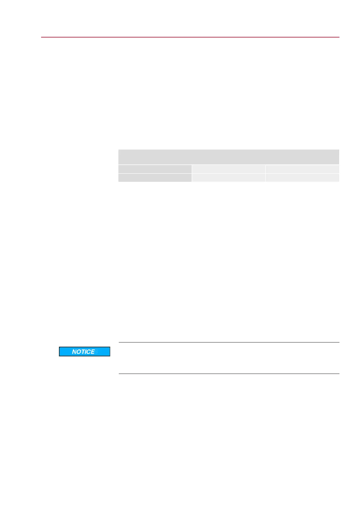
Table 8:
Fuse for heating system
Designation in wiring diagram = F4 ext.
230 V AC115 V ACExternal power supply
1 A T2 A TFuse
If actuator controls are mounted separately from actuator ( actuator controls on wall
bracket): Consider length and cross section of connecting cable when defining the
protection required.
Information
Separate mounting (actuator controls on wall bracket) requires prior consent of
AUMA.
Potential of customer
connections
All input signals (control inputs) must be supplied with the same potential.
All output signals (status signals) must be supplied with the same potential.
Safety standards
Safety measures and safety equipment must comply with the respectively valid
national on site specifications. All externally connected devices shall comply with
the relevant safety standards for the place of installation.
Connecting cables
Cable glands
Reductions
Blanking plug
●
We recommend using connecting cables and connecting terminals according
to rated current (I
N
) (refer to motor name plate or electrical data sheet).
●
For device insulation, appropriate (voltage-proof) cables must be used. Specify
cables for the highest occurring rated voltage.
●
Use connecting cable with appropriate minimum rated temperature.
●
For connecting cables exposed to UV radiation (outdoor installation), use UV
resistant cables.
●
For the connection of position transmitters, screened cables must be used.
Cable installation in ac-
cordance with EMC
Signal and fieldbus cables are susceptible to interference. Motor cables are
interference sources.
This product potentially causes high frequency interference!
→
The measures eliminating interference described hereafter must be observed
for cable installation in accordance with EMC.
●
Use shielded power cable and earth shield at both ends.
●
Lay cables being susceptible to interference or sources of interference at the
highest possible distance from each other.
●
The interference immunity of signal and fieldbus cables increases if the cables
are laid close to the earth potential.
●
If possible, avoid laying long cables and make sure that they are installed in
areas being subject to low interference.
●
Avoid parallel paths with little cable distance of cables being either susceptible
to interference or interference sources.
21
SQV 05.2 – SQV 14.2 / SQRV 05.2 – SQRV 14.2 Control unit: electronic (MWG)
ACV 01.2 Non-Intrusive Profinet Electrical connection

 Loading...


