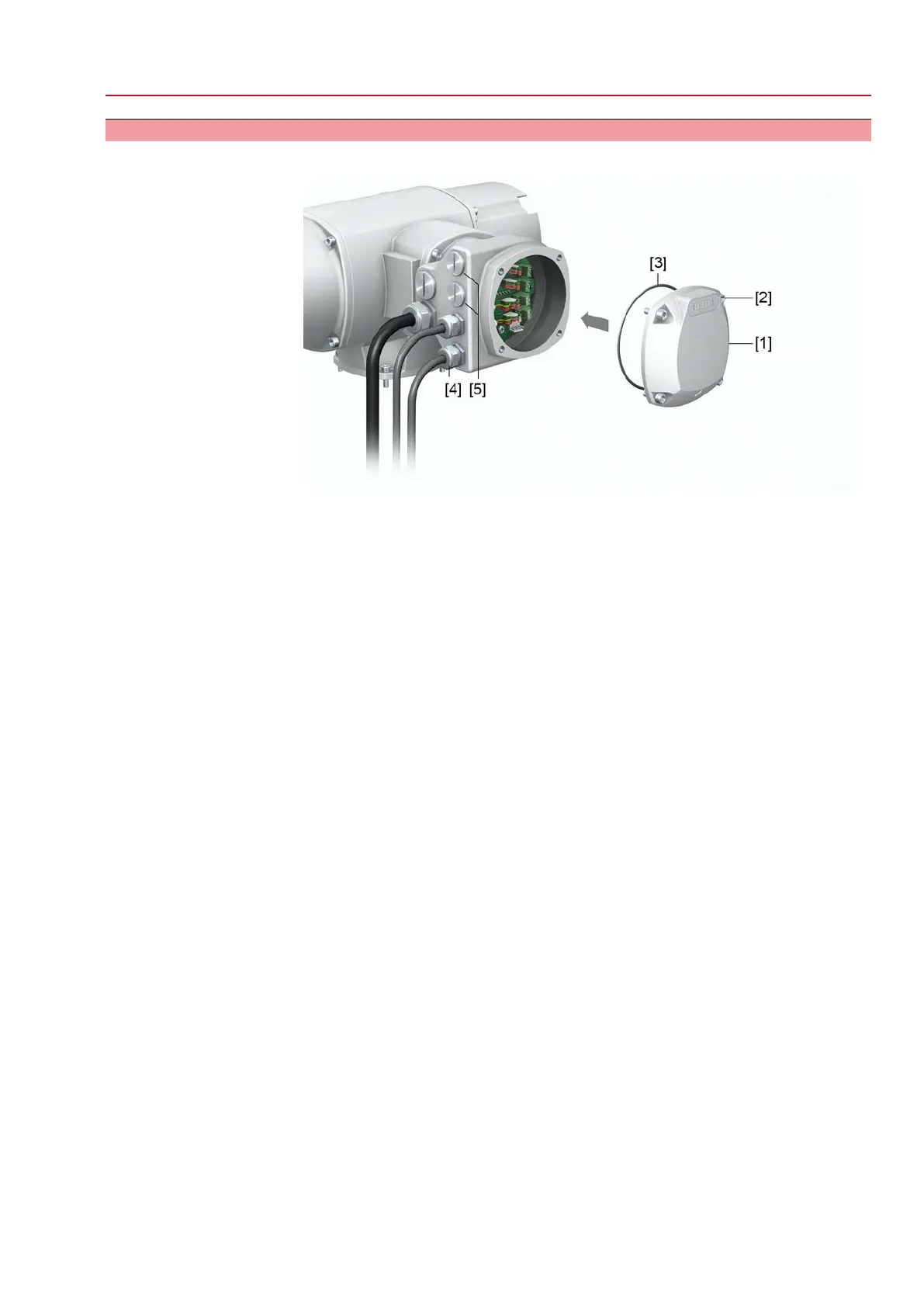
Figure 27: Profinet connection board with RJ-45 connections
n–1 Profinet cable from previous device
n+1 Profinet cable to next device
(For line topology or redundant ring/MRP - Media Redundancy Protocol)
Profinet connection is made via RJ-45 ports by means of connectors for field
assembly.The scope of delivery includes one RJ-45 Profinet connector for Cat.5
(supplied within electrical connector). Further connectors are available with AUMA
(e.g. for line topology or redundant ring) on request.
Order designations:
●
RJ-45 Profinet connector for Cat.5 (as included in scope of delivery): AUMA
article number K009.706
●
Option: RJ-45 Profinet connector for Cat.6
A
cables: AUMA article number
K009.705
Table 15:
Assignment of RJ-45 Profinet port
PinColour of wire insula-
tion
FunctionSignal
1YellowTransmit Data +TD +
2OrangeTransmit Data –TD –
3WhiteReceive Data +RD +
6BlueReceive Data –RD –
Description of LEDs on connection board
Table 16:
ExplanationStatusMODS (Module Status)
No voltage or module in “SETUP” or “NW_INIT”
status
Not InitialisedRed LED: off +
Green LED: off
The module has aborted “NW_INIT” statusNormal OperationGreen LED: illuminated
Diagnostic events availableDiagnostic EventsGreen LED: 1 brief pulse
Device in “EXCEPTION” statusException ErrorRed LED: illuminated +
Red NETS LED: off
Internal device errorFatal EventRed LED: illuminated +
Red NETS LED: illuminated
Do not cut power supply!Firmware updateGreen/Red LEDs:
Alternately blinking
29
SQV 05.2 – SQV 14.2 / SQRV 05.2 – SQRV 14.2 Control unit: electronic (MWG)
ACV 01.2 Non-Intrusive Profinet Electrical connection

 Loading...


