6.2.5. Profinet cables: connect
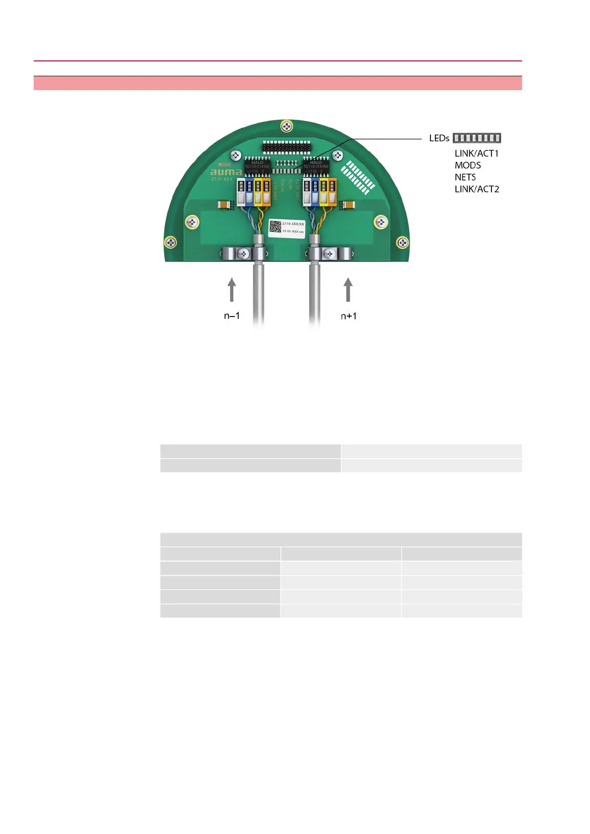
Figure 26: Profinet connection board with connection terminals
n–1 Profinet cable from previous device
n+1 Profinet cable to next device
(For line topology or redundant ring/MRP - Media Redundancy Protocol)
Profinet connection is made individually by means of a safe Ethernet-capable
insulation displacement connection.The colour coding of connection terminals are
matching the Ethernet cable according to Profinet (white/blue/yellow/orange).
Table 13: Connecting data
0.2 mm² – 0.34 mm² / AWG 24 – AWG 22Connection capacity (solid wire)
0.2 mm² – 0.34 mm² / AWG 24 – AWG 22Connection capacity (stranded)
1. Remove cable sheathing and clamp shield under strain relief.
2. Connect cables to connection terminals. For this, use a small screwdriver to lift
or push down the levers.
Table 14:
Connection terminal assignment
Colour of wire insulationFunctionSignal
YellowTransmit Data +TD +
OrangeTransmit Data –TD –
WhiteReceive Data +RD +
BlueReceive Data –RD –
Option:
28
SQV 05.2 – SQV 14.2 / SQRV 05.2 – SQRV 14.2 Control unit: electronic (MWG)
Electrical connection ACV 01.2 Non-Intrusive Profinet

 Loading...


