11. Commissioning (settings in the actuator)
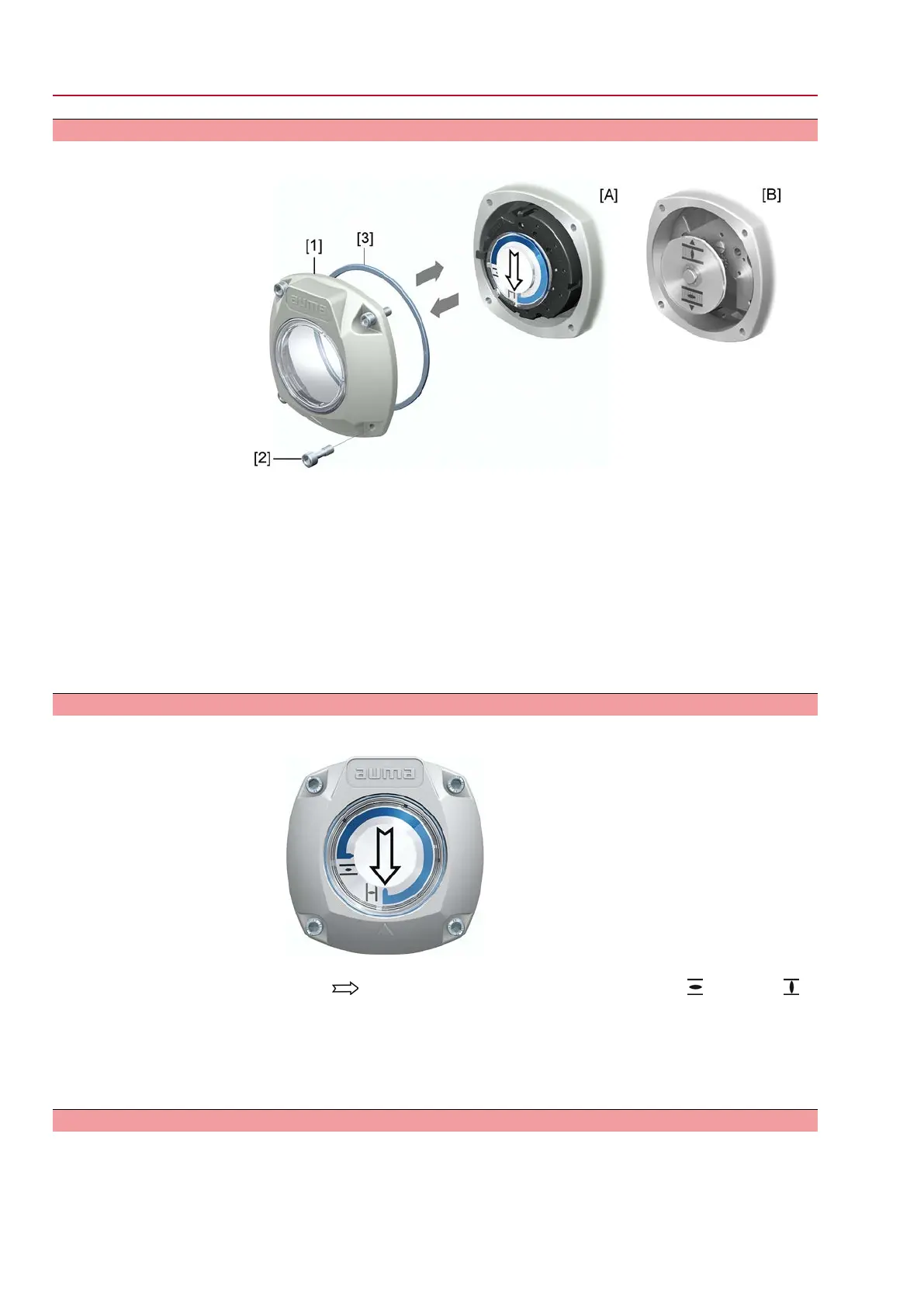
Figure 67: Mechanical position indicator (self-adjusting)
The actuator is supplied with the swing angle set in the factory in compliance with
the order. The mechanical position indication is set to this swing angle.
If the factory swing angle is changed at a later date, the position indicator must be
adapted to the new swing angle:
●
Increasing the swing angle: The mechanical position indication automatically
adjusts with the subsequent operation.
●
Decreasing the swing angle:The mechanical position indication must be newly
set (refer to the subsequent chapters).
Figure 68: Mechanical position indication via indicator mark (not self-adjusting)
In case the mechanical position indication integrated within the actuator is NOT
self-adjusting, the switch compartment must be opened for mechanical position
indication adjustment when commissioning.
62
SQV 05.2 – SQV 14.2 / SQRV 05.2 – SQRV 14.2 Control unit: electronic (MWG)
Commissioning (settings in the actuator) ACV 01.2 Non-Intrusive Profinet

 Loading...


