6.2. SF electrical connection (AUMA plug/socket connector)
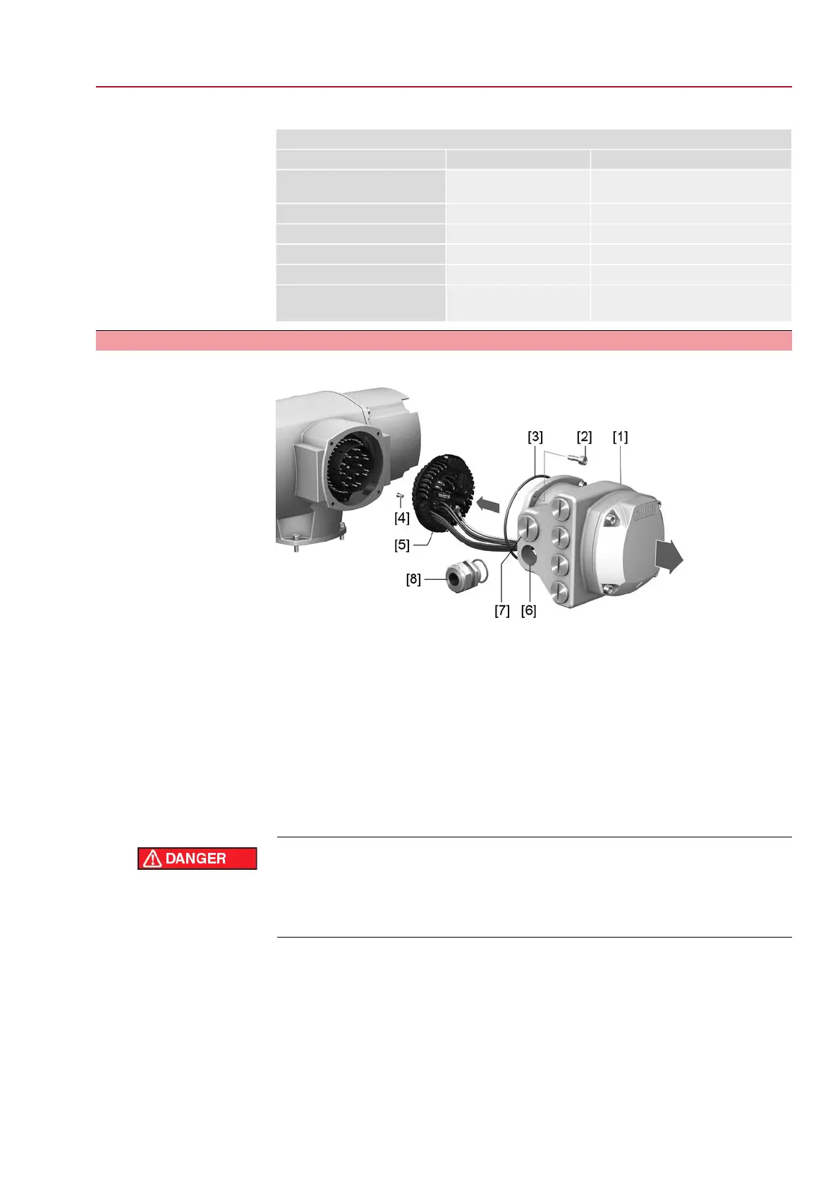
Figure 19: SF electrical connection
[1] Terminal compartment (in cover)
[1A] Cable entries for mains connection (power and control contacts)
[1B] Cable entries for fieldbus cables
[2] Socket carrier with screw-type terminals
Short description
Plug-in electrical connection with screw-type terminals for power and control contacts.
Control contacts also available as crimp-type connection as an option.
SF version. For power and control cable connection, remove the AUMA plug/socket
connector and the socket carrier from terminal compartment. Removing the cover
is sufficient for connecting the fieldbus cables.
Technical data
Table 11:
Electrical connection via AUMA plug/socket connector
Control contactsPower contacts
50 pins/sockets6 (3 equipped) + protective
earth conductor (PE)
No. of contacts max.
1 to 50U1, V1, W1, U2, V2, W2, PEDesignation
250 V750 VConnection voltage max.
16 A25 ARated current max.
Screw connection, crimp-type (option)Screw connectionType of customer connection
2.5 mm
2
(flexible or solid)
6 mm
2
(flexible)
10 mm
2
(solid)
Connection diameter max.
23
SQV 05.2 – SQV 14.2 / SQRV 05.2 – SQRV 14.2 Control unit: electronic (MWG)
ACV 01.2 Non-Intrusive Profinet Electrical connection

 Loading...


