12
C. SPD Breaker
D. SPD
E. Auxiliary AC Main Fuse
F. Auxiliary RCCB
G. Cable Gland Plate
H. Charging Module
I. Heater Circuit Fuse
J. Contactor Circuit Fuse
K. 48V Auxiliary AC Fuse
L. 24V Auxiliary AC Fuse
M. PE Busbar — connects the PE cable
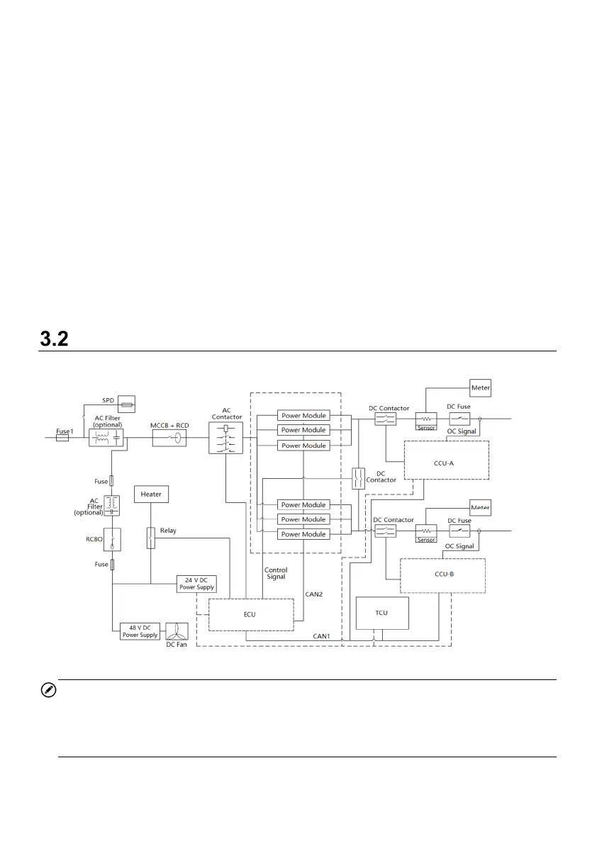
Working Principle Diagram
Figure 3-3 Working Principle View
NOTE
Fuse 1 is used when the power rate of the MaxiCharger exceeds 120 kW.
The number of used power modules varies according to the power rate of the
MaxiCharger.