Hardware Installation Guide 45
Wheel Angle Sensor Installation Guidelines
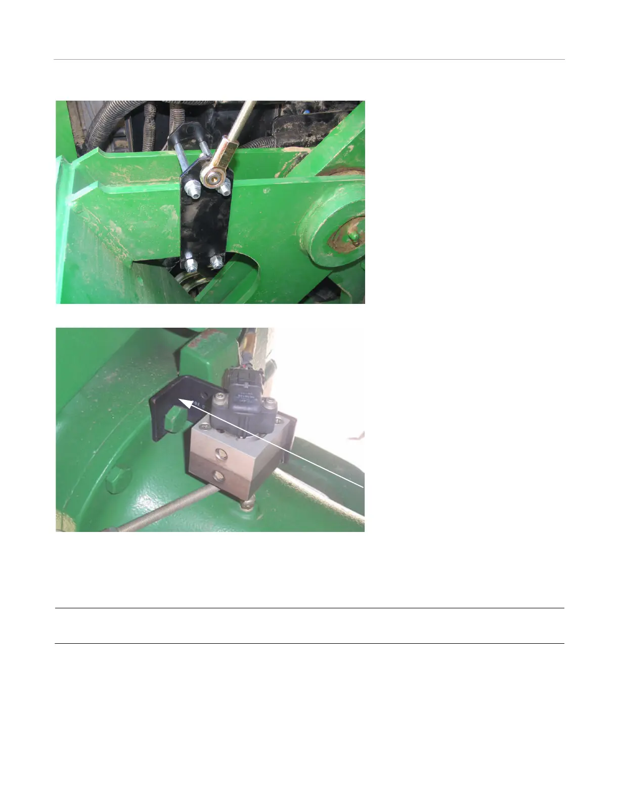
Figure 4-11 Linkage Bracket Mounting (side view)
Figure 4-12 Wheel Angle Sensor Bracket
Adjust linkage arm length and/or linkage bracket position to obtain approximately 3000 counts. Turn the tractor all the way
right and left to make sure the linkage arms can move without interference. Note: This step is done after final assembly during
the calibration and tuning steps. Do not turn the steering until the installation is complete and the count is confirmed in the
Examine Steering screen.
Note: The threaded linkage rods must be cut to the correct lengths before final assembly. The linkage rods are shown
assembled in Figure 4-13.
Wheel Angle
Sensor Bracket