9. Modbus Mapping Table
54
© Copyright Reserved Autonics Co., Ltd.
-|Transparent setting guide|-
9. Modbus Mapping Table
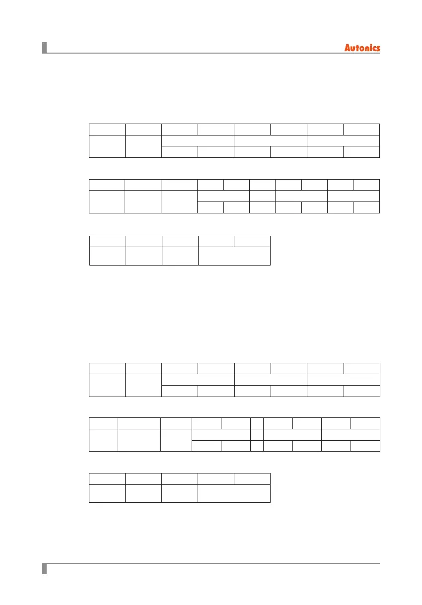
9.1 Function code 3 (0×03) = Read holding resisters
(1) Request
(2) Response
(2) Response
※
Exception code
0×01: Not supported command code.
0×02: Starting address of required data and transmittable address are dierent.
0×03: The number of required data is over than the number of transmittable data.
0×04: Transmittable data does not process properly.
9.2 Function code 4 (0×04) = Read input resisters
(1) Request
※
Exception code
0×01: Not supported command code.
0×02: Starting address of required data and transmittable address are dierent.
0×03: The number of required data is over than the number of transmittable data.
0×04: Transmittable data does not process properly.
(3) Error
(3) Error
Master to Slave
Master to Slave
Slave to Master
Slave to Master
Slave to Master
Slave to Master
0×01 0×03 0×00 0×00 0×00 0×16 ×× ××
Add.
Com-
mand
Start address Number of data CRC 16
High Low High Low High Low
0×01 0×03 0×10 0×03 0×E8 ... 0×03 0×E8 ×× ××
Add.
Response
command
Number of
data
1st data ... 16th data CRC 16
High Low ... High Low High Low
0×01 0×83 ×× ×× ××
Address
Response
command
Exception
code
CRC 16
0×01 0×04 0×00 0×00 0×00 0×10 ×× ××
Address Command
Start address Number of data CRC 16
High Low High Low High Low
0×01 0×84 ×× ×× ××
Address
Response
command
Exception
code
CRC 16
0×01 0×04 0×10 0×03 0×E8 ... 0×03 0×E8 ×× ××
Address
Response
command
Number
of data
1st data ... 16th data CRC 16
High Low ... High Low High Low
 Loading...