9. Modbus Mapping Table
55
© Copyright Reserved Autonics Co., Ltd.
-|Transparent setting guide|-
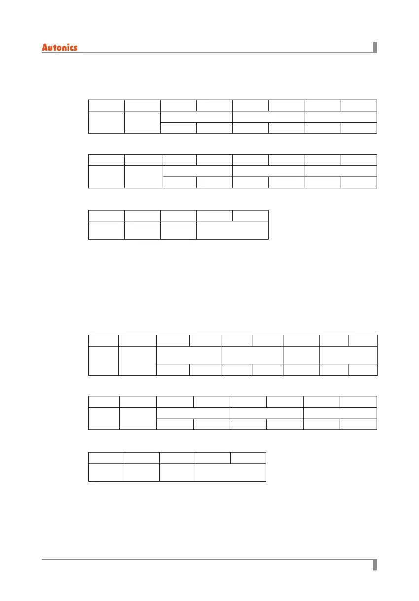
9.3 Function code 6 (0×06) = Write single resisters
(1) Request
※
Exception code
0×01: Not supported command code.
0×02: Starting address of required data and transmittable address are dierent.
0×03: The number of required data is over than the number of transmittable data.
0×04: Transmittable data does not process properly.
9.4 Function code 16 (0×10) = Write multiple resisters
(1) Request
※
Exception code
0×01: Not supported command code.
0×02: Starting address of required data and transmittable address are dierent.
0×03: The number of required data is over than the number of transmittable data.
0×04: Transmittable data does not process properly.
0×01 0×06 0×00 0×00 0×03 0×E8 ×× ××
Address Command
Station Data CRC 16
High Low High Low High Low
0×01 0×06 0×00 0×00 0×03 0×E8 ×× ××
Address Command
Station Data CRC 16
High Low High Low High Low
0×01 0×86 ×× ×× ××
Address
Response
command
Exception
code
CRC 16
Master to Slave
Master to Slave
Slave to Master
Slave to Master
Slave to Master
Slave to Master
(2) Response
(2) Response
(3) Error
(3) Error
0×01 0×10 0×00 0×00 0×00 0×10 0×20 ×× ××
Address Command
Start address Number of data
Number of
byte
CRC 16
High Low High Low High Low
0×01 0×10 0×00 0×00 0×03 0×E8 ×× ××
Address Command
Station Data CRC 16
High Low High Low High Low
0×01 0×90 ×× ×× ××
Address
Response
Command
Exception
code
CRC 16

 Loading...