6. Parameter Setting and Functions
43
© Copyright Reserved Autonics Co., Ltd.
-|Transparent setting guide|-
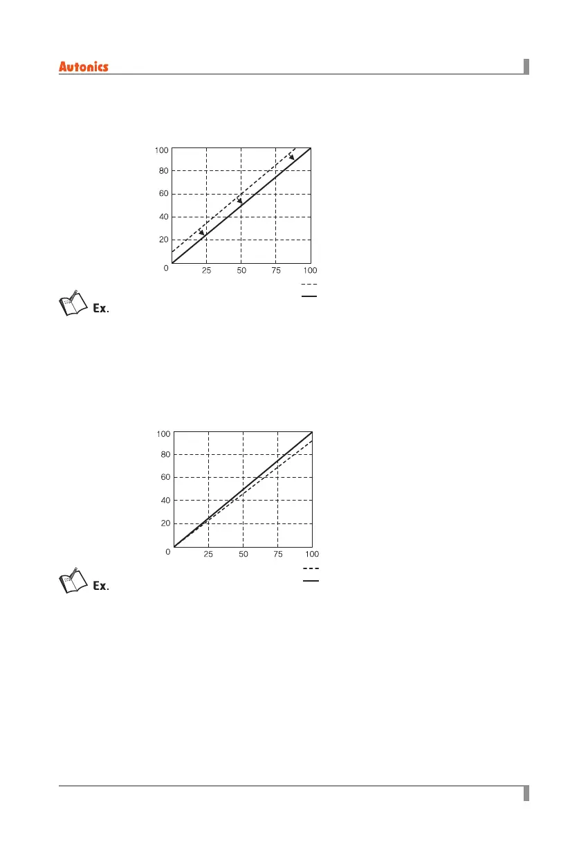
6.2.12 Input slope correction [
SPAN
]
It compensates the slope of the measured 100% input for actual 100% input value.
• Setting range: -99.9 to 99.9 (unit: %)
Input type is 4 to 20mA.
When 20mA is applied and the input monitor value displays 99.5%, set
SPAN
as
0.5
and the input
monitor value is 100.0%.
6.2.13 Display value content [
DISP
], bar graph content [
BAR
]
You can select display value content for the display part and bar graph in RUN mode.
• Display range
- Single-phase: [
LD-V
], [
AMP
], [
KW
], [
REF
]
- 3-phase: [
U-V
], [
V-W
], [
W-U
], [
LA-U
], [
LA-V
], [
LA-W
], [
KW
], [
REF
]
Actual input signal(%)
Input corrected signal(%)
Measured
input signal
(%)
Actual input signal (%)
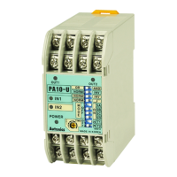
6.2.11 Input correction[
IN-B
]
It compensates the oset between actual input value and measured input value.
• Setting range: -99.9 to 99.9 (unit: %)
Actual input signal(%)
Input corrected signal(%)
Measured
input signal
(%)
Actual input signal (%)
Input type is 4 to 20mA,
When 4mA is applied and the input monitor value displays 0.5%, set
IN-B
as
-0.5
and the input
monitor value displays as 0.0%.

 Loading...