8. Maintenance
53
© Copyright Reserved Autonics Co., Ltd.
-|Transparent setting guide|-
8.2 Thyristor (SCR)
There is one output SCR element in single-phase model (DPU1 Series), and three output SCR
elements in 3-phase model (DPU3 Series).
It is normal status when the resistance between K and G is 10 to 100Ω during checking SCR
elements.
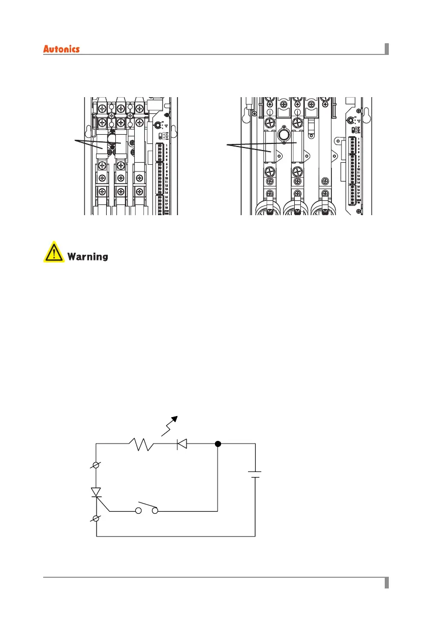
Refer to the below circuit diagram for accurate maintenance.
Assemble this unit as below circuit diagram. (Load indicator turns OFF)
When shorting TEST 1 at gate momentarily, open it to turn ON the load indicator.
When the load indicator does not turn ON, SCR elements are bad conditions.
LOAD
TEST 1
9V
A
B
G
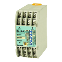
8.1.2 3-phase (DPU3 series)
Fuse position by each model
● Use the designated Fuse.
● After changing the fuse, you must check the fuse is installed correctly.
Fuse
Fuse
A type B, C, D type
 Loading...