6. Parameter Setting and Functions
44
© Copyright Reserved Autonics Co., Ltd.
-|Transparent setting guide|-
①
Increase rate of load resistance [
UP
]
It is based on 100% of load resistance(R), 1Ω . When disconnected R
1
to R
5
, load resistance is
2Ω and load resistance [
RES
] in monitoring mode displays 200%.
②
Decrease rate of number of loads [
DOWN
]
It is based on 100% of 10 loads (R
1
to R
10
). When disconnected R
1
to R
5
, the number of load
are 5(R
6
to R
10
) and load resistance [
RES
] in monitoring mode displays 50%.
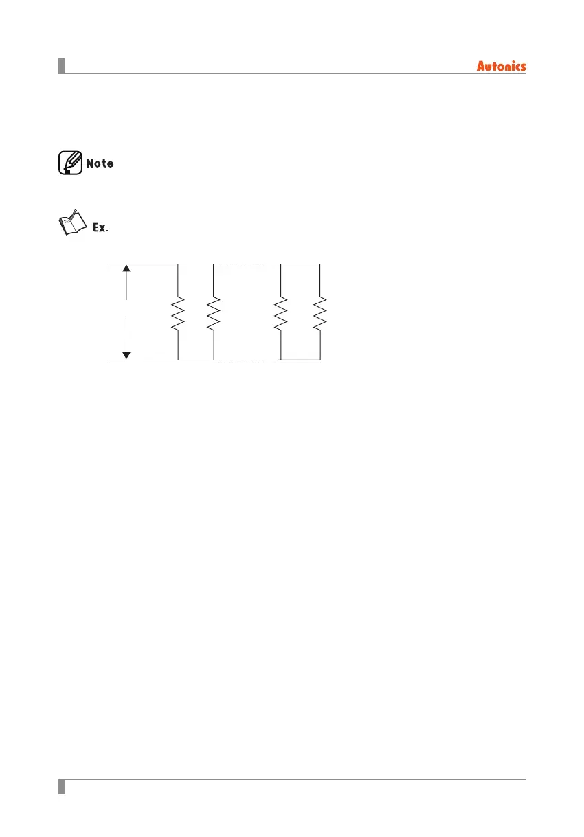
R
1
to R
10
= 10Ω of each and load resistance (R) =1Ω
When disconnecting R
1
to R
5
,
R
R
1
R
2
R
9
R
10
6.2.14 Load resistance display method [
DRES
]
This function is for display load resistance [
RES
] into a percentage in monitoring mode when
disconnecting the parallel load. You can select this value as increase rate of load resistance [
UP
]
or as decrease rate of number of loads [
DOWN
].
Decrease rate of number of loads [
DOWN
] displays correct decrease rate only when the connected
each load resistance is same.

 Loading...