Table of Contents
13
© Copyright Reserved Autonics Co., Ltd.
-|Transparent setting guide|-
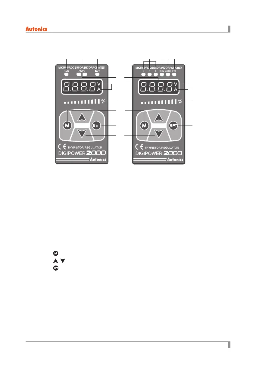
1.3 Unit description
①
RUN indicator: Turns ON in RUN, turns OFF in STOP.
②
AUTO indicator: Turns ON in AUTO, turns OFF in MANUAL.
③
EVT indicator: Turns ON in Digital Input (DI-1 to 3) ON, ashes in alarm output.
④
R, S, T lamp: Turns ON dierently by displayed value in display part.
E.g.) When R, S lamps turn ON, it displays voltage between R-S line
⑤
Display part: Displays selected display value content in RUN mode, displays parameter and set
value in SET mode.
⑥
V, A indicators: The V indicator turns ON when displaying voltage.
The A indicator turns ON when displaying current.
The V, A indicators turn ON when displaying power.
The V, A indicators turn OFF when displays resistance and input value.
⑦
Bar display: Turns ON as 0 to 100% ratio for selected display value.
⑧
key: Used to enter parameter mode, monitoring mode and to move between parameters.
⑨
, key: Used to move setting modes and to set parameters.
⑩
key: Used to return to RUN mode from SET mode
<Single-phase> <3-phase>
① ①④ ②② ③③
⑤
⑧
⑥
⑦
⑩ ⑩
⑨
⑦
⑥

 Loading...