19
2PRODUCT DESCRIPTION
2.1 OVERVIEW
ALS
20x
256
Sensor connections
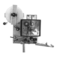
[9] Arrangement of the sensor connections (schematic) on the LH
(left figure) and RH (right figure) devices:
A Product sensor
B Signal outputs (optional)
C Signal inputs (optional)
D Rotary encoder (for automatic speed adaption)
E Roll diameter sensor
F Label sensor
G (ALS 20x) Alternative label sensor
H (ALS 256) Alternative label sensor
For information on connecting the sensors, see
section “Connecting sensors” on page 40.
[8] Sensor connections on the ALS 20x (RH)
START
PLC-OUT
PLC-IN
LABEL
ROTARY
ENCODER
OD
CAP
CAP for 256
START
PLC-OUT
PLC-IN
LABEL
ROTARY
ENCODER
OD
CAP
CAP for 256
RHLH
A
B C
F
D E
G
A
C B
E D
F
G
H H