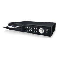
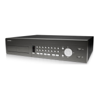
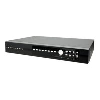
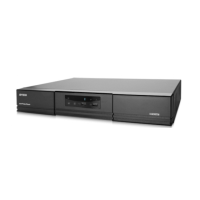
CONNECTIONS AND SETUP
-11-
3) Power connection
Connect the camera with indicated power supply and make sure it’s power-supplied.
3.2.2 Speed Dome Camera Connection
The following description is taking our brand’s speed dome camera as an example. For detailed PIN / port
connection, please refer to “APPENDIX 1 PIN CONFIGURATION” at page 51; for DVR setting to control the speed
dome camera, please refer to “7.1.8 Remote” at page 30.
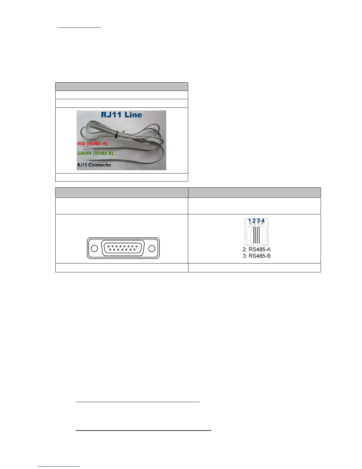
RJ11 cable
RS485-A: Red wire
RS485-B: Green wire
The RJ11 cable is not supplied in the sales package.
15 PIN D-Sub Connector
RS-485 Port
RS485-A: PIN 11
RS485-B: PIN 10
RS485-A: PIN 2
RS485-B: PIN 3
Solder Side of
15-pin D-Sub connector
1
912131415
16 17
2345678
1011
RS485 -A: PIN11 / RS485-B: PIN1 0
D-Sub connector is supplied with the DVR package. Example of RS485 port on the DVR rear panel.
STEP 1: Get a RJ11 cable with the proper length to your connection.
Different RJ11 connector may have different wire layout, so the connection might be different. If you
cannot control the DVR after connection, please reverse the RJ11 cable connection with the DVR.
STEP 2: Remove one end of the insulating coating of the RJ11 cable.
Remove one end of the insulating coating of the RJ11 cable to find the RS485-A and the RS485-B wires,
and remove the insulating coating to reveal the naked wires for further connection.
STEP 3: Twist the RS485-A and RS485-B wires of the RJ11 cable and the speed dome camera together.
Twist the RS485-A (red) and RS485-B (green) wires of the RJ11 cable to the RS485-A (brown) and
RS485-B (orange) wires of the speed dome camera. To protect the naked wires, use the insulation tape
to cover on the twisted wires.
STEP 4: Connect the other end of the RJ11 cable to DVR.
When there’s an RS485 port on the DVR real panel
Connect the other end of the RJ11 cable without removing the insulating coating directly to the RS485
port on the DVR real panel.
When there’s an external I/O port on the DVR real panel
Solder the RS485-A (red) and RS485-B (green) wires of the RJ11 cable to the corresponding pins on the
solder side of the 15 PIN D-Sub connector (as shown in the picture above).