APPENDIX 1 PIN CONFIGURATION
~52~
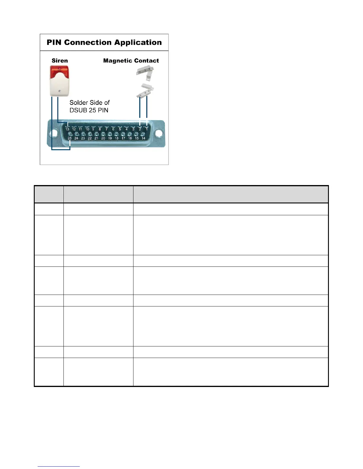
‧ For Model 2 & 6
Siren: When the DVR is triggered by alarm or motion, the COM
connects with NO and the siren with strobe starts wailing and
flashing.
Magnetic Contact: When the magnetic contact is opened, the
alarm will be triggered and the recording is on.
PIN FUNCTION DESCRIPTION
1
GND GROUND
2~5
ALARM INPUT
Connect ALARM INPUT (PIN 2 – 5) and GND (PIN 1) connector with wires. Once an
alarm is triggered, the DVR will start recording and the buzzer will be on.
PIN 2 is Alarm 1. Once the alarm is triggered, the CH1 of the DVR will start alarm-triggered recording.
PIN 3 is Alarm 3. Once the alarm is triggered, the CH3 of the DVR will start alarm-triggered recording.
PIN 4 is Alarm 5. Once the alarm is triggered, the CH5 of the DVR will start alarm-triggered recording.
PIN 5 is Alarm 7. Once the alarm is triggered, the CH7 of the DVR will start alarm-triggered recording.
6 ~ 12
PIN OFF NA
13
EXTERNAL ALARM NO.
Under the normal operation, COM disconnects with NO. But when any alarm is
triggered, COM connects with NO.
Attention: The voltage restriction is under DC24V 1A.
14
PIN OFF NA
15~18
ALARM INPUT
Connect ALARM INPUT (PIN 15 – 18) and GND (PIN 1) connector with wires. Once
an alarm is triggered, the DVR will start recording and the buzzer will be on.
PIN 15 is Alarm 2. Once the alarm is triggered, the CH2 of the DVR will start alarm-triggered recording.
PIN 16 is Alarm 4. Once the alarm is triggered, the CH4 of the DVR will start alarm-triggered recording.
PIN 17 is Alarm 6. Once the alarm is triggered, the CH6 of the DVR will start alarm-triggered recording.
PIN 18 is Alarm 8. Once the alarm is triggered, the CH8 of the DVR will start alarm-triggered recording.
19~24
PIN OFF NA
25
EXTERNAL ALARM COM
Under the normal operation, COM disconnects with NO. But when any alarm is
triggered, COM connects with NO.
Attention: The voltage restriction is under DC24V 1A.