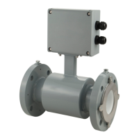
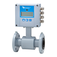
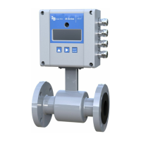
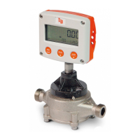
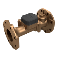
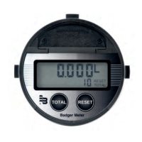
The National Electronics Manufacturer's Association (NEMA) 6P enclosures are constructed for indoor or outdoor use. The 6P
enclosures provide protection against access to hazardous parts. They also provide a degree of protection against ingress of
solid foreign objects and water (hose directed water and the entry of water during prolonged submersion at a limited depth)
which provide an additional level of protection against corrosion and that are not damaged by the external formation of ice
on the enclosure.
Temperature Ranges
TO PREVENT DAMAGE TO THE METER, STRICTLY OBSERVE THE TRANSMITTER’S AND SENSOR’S MAXIMUM
TEMPERATURE RANGES.
• To prevent damage to the meter, strictly observe the transmitter and sensor temperature ranges.
• In regions with extremely high ambient temperatures, protect the sensor from extreme temperatures.
• In cases where fluid temperature exceeds 212° F (100° C), use the remote mount version.
Transmitter Ambient temperature –4…140° F (–20…60° C)
Sensor Fluid temperature
PTFE/PFA –40…302° F (–40…150° C)
Hard rubber 32…176° F (0…80° C)
Soft rubber 32…176° F (0…80° C)
Protection Class
To fulfill requirements of the protection class, follow these guidelines:
• Make sure body seals are undamaged and in proper condition.
• Firmly screw in all the body screws.
• Outer diameters of the wiring cables must correspond to cable inlets (for M20 Ø 5....10 mm). In cases where cable inlet is
not used, put in a dummy plug.
• Tighten cable inlets.
• If possible, lead cable away downwards to prevent humidity from entering cable inlet.
The standard option is protection class IP 67. If you require a higher protection class, use the remote mount version. NEMA
6P/IP 68 is an option for the sensor with the remote mount version.
Pipelines and Fluid Flow
Take the following precautions during installation:
• Do not install the meter on pipes with extreme vibrations. If pipes are vibrating, secure the piping with appropriate pipe
supports in front of and behind the meter. If vibrations cannot be restrained, use the remote mount option.
• Do not install the sensor close to pipeline valves, fittings or impediments that can cause flow disturbances.
• For sensors with PTFE liners, do not install the sensor on suction sides of pumps.
• Do not install the sensor on outlet sides of piston or diaphragm pumps. Pulsating flow can affect meter performance.
• Avoid installing the sensor near equipment that produces electrical interference such as electric motors, transformers,
variable frequency or power cables.
• Make sure both ends of the signal cables are securely fastened.
• Place power cables and signal cables in separate conduits.
• Place the meter where there is enough access for installation and maintenance tasks.
• Install the meter with the forward flow label on the meter body matching the pipeline flow.
Meter Location, Orientation and Applications
Page 10 March 2022MAG-UM-01272-EN-21

 Loading...
