METER LOCATION, ORIENTATION AND APPLICATIONS
Gasket and grounding requirements must be considered when determining the meter location, orientation and application.
See “Meter Gaskets and Grounding” on page 15. There are two transmitter mounting options: a meter mount option and a
remote mount option.
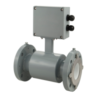
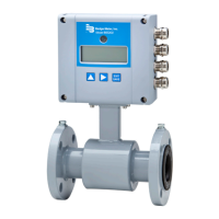
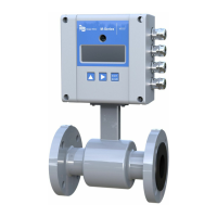
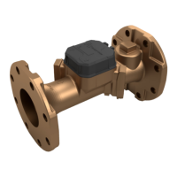
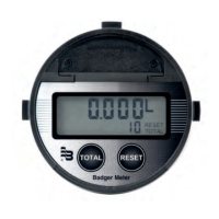
Meter mount Remote mount
Figure 5: Transmitter mounting options
Transmitter Mounting Conguration Options
There are two configuration options for mounting the transmitter and many options to accommodate a variety of
meter-placement and environmental conditions.
Meter Mount Configuration
The meter mount configuration has the transmitter mounted directly on the sensor. This compact, self-contained
configuration minimizes installation wiring.
Remote Mount Configuration
The remote mount configuration places the transmitter at a location away from the fluid flow and sensor. This is necessary in
situations where process fluid temperature or the environment exceeds transmitter ratings.
The sensor and transmitter are connected by wires, run through conduit, between junction boxes on the sensor and the
transmitter. The distance between the sensor junction box and transmitter junction box can be up to 500 feet (150 meters). A
remote mounting bracket is supplied.
Use the remote version in the following cases:
• Sensor protection class IP 68
• Fluid temperature > 212° F (100° C)
• Strong vibrations
Remote Transmitter Outdoor Location
The transmitter can be installed and operated outdoors. However, it must be protected from the elements, as follows:
• The ambient environment/temperature rating for the unit is –4…140° F (–20…60° C).
• If an indoor location is within 500 feet (150 meters) of the sensor, consider increasing the cable length and mounting the
transmitter indoors.
• At minimum, fabricate a roof or shield over and/or around the transmitter to protect the LCD screen from direct sunlight.
• Do not install the signal cable close to power cables, electric machines or similar.
• Fasten signal cables. Due to capacity changes, cable movements may result in incorrect measurements.
Submersible Option
If you are installing the meter in a vault, order the remote transmitter option. Do not install the transmitter inside a vault.
We also recommend ordering the remote meter package with the submersible option (NEMA 6P / IP68). This eliminates any
potential problems resulting from humidity or temporary flooding in the vault.
Meter Location, Orientation and Applications
Page 9 March 2022 MAG-UM-01272-EN-21

 Loading...
