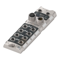
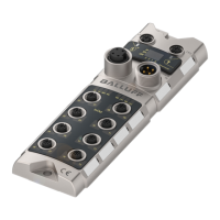
Home
Balluff
Control Unit
BNI ECT-507-005-Z040
Balluff BNI ECT-507-005-Z040 User Manual
5
of 1
of 1 rating
37 pages
Give review
Manual
Specs
To Next Page
To Next Page
To Previous Page
To Previous Page
Loading...
www.balluff.com
34
8
Appendix
8.1.
Included in the
Scope of Delivery
The BNI ECT comprises the following elements:
•
IO
-Link block
•
4x M12 dummy plugs
•
Ground strap
•
M4x6 screw
•
20 informational signs
8.2.
Order number
BNI ECT-5x7-
005
-Z040
Balluff Network Interface
EtherCAT™
Functions
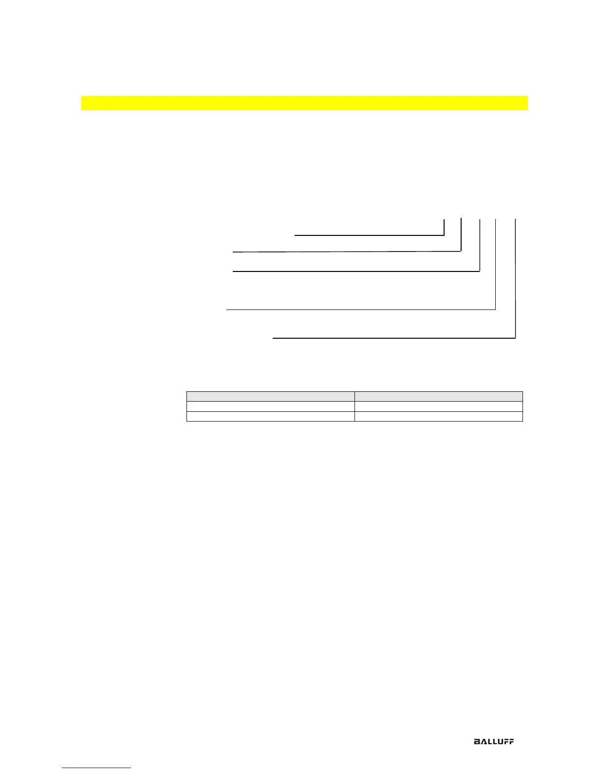
507 = 4 IO-Link Ports Class A
527 = 4 IO-Link Ports Class B
Variants
005 = 2-Port-Switch
Mechanical version
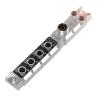
Z040 = IO-Link Minimaster housing made of die-
ca
st zinc
Data transmi
ssion: 2 x M12x1 internal thread
Pow
er: 7/8“ external thread
Sensor connect
ions: 4 x M12x1 internal thread
8.3.
Ordering
information
Product order code
Order code
BNI ECT-
507
-
005
-Z040
BNI009U
BNI ECT-
527
-
005
-Z040
BNI00AC
34
36
Table of Contents
Default Chapter
2
Table of Contents
2
Inputs Pin
3
Outputs Pin
3
Pin 4 / Pin
3
1 General
4
Structure of the Manual
4
Typographical Conventions
4
Enumerations
4
Actions
4
Syntax
4
Cross-References
4
Symbols
4
Abbreviations
4
Differing Views
4
2 Safety
5
Intended Use
5
Installation and Startup
5
General Safety Notes
5
Resistance to Aggressive Substances
5
Dangerous Voltage
5
3 First Steps
6
Module Overview
6
Mechanical Connection
7
Electrical Connection
7
Power Supply
7
Grounding
7
Ethercat™ Interface
7
IO-Link Port
8
4 Technical Data
9
Dimensions
9
Mechanical Data
9
Operating Conditions
9
Electrical Data
9
Ethernet
9
Function Indicators
10
Module Status
10
Port
10
5 Integration
11
Ethercat
11
Device Data
11
Input/Output Buffer
11
Project Planning
11
Integration into Project Planning Software
12
Installing ESI Files
12
Automatic Scanning
12
Manually Attach Device
13
Required Setting on the Device
14
Station Alias
15
Configuring IO-Link Module
16
Bit Mapping and Function
17
Inputs Pin 4
17
Outputs Pin 4
17
IO-Link Modules
17
SIO Module
17
Short-Circuit
17
Restart Pin 4 / Pin 2 (Class a Only)
17
IO-Link State
18
Sensor Short Circuit
18
Startup
19
Configuration of the Modules
19
Validation
20
Parameter Server
20
Upload Flag on the IO-Link Device
21
Safe State
21
IO-Link Parameterization
22
Control
22
Status
22
Example - Coe Setting
22
Example - Read
23
Example - Write
23
6 Object List
24
Input Process Data (Pin 2) Ch. X (0X2000 - 0X2Fff)
24
Input Process Data (Pin 4) Ch. X (0X2000 - 0X2Fff)
24
Additional IO-Link Configuration Data (Pin 4) Ch. X (0X2000 - 0X2Fff)
24
Additional IO Configuration Data (Pin 2) Ch. X (0X2000 - 0X2Fff)
24
Module Status (0X2A02)
24
Output Process Data Ch. X (0X3000 - 0X3Fff) (Class a Only)
24
IO-Link Service Data Ch. X (0X4000 - 0X4Fff)
24
IO-Link Configuration Data Ch. X (0X8000 - 0X8Fff)
25
IO-Link Information Data Ch. X (0X9000 - 0X9Fff)
25
IO-Link Diagnosis Data Ch. X (0Xa000 - 0Xafff)
25
IO-Link Status Data Ch. X (0Xf100)
25
Configuration Without ESI
26
Master Control
26
Process Data Length
26
Example
26
7 Web Server
27
General
27
Navigation / Help
28
Login/Logout
29
Home" Dialog
30
Ports" Dialog
32
Configuration" Dialog
33
Log" Dialog
34
8 Appendix
35
Included in the Scope of Delivery
35
Order Number
35
Ordering Information
35
Notes
36
5
Based on 1 rating
Ask a question
Give review
Questions and Answers:
Need help?
Do you have a question about the Balluff BNI ECT-507-005-Z040 and is the answer not in the manual?
Ask a question
Balluff BNI ECT-507-005-Z040 Specifications
General
Brand
Balluff
Model
BNI ECT-507-005-Z040
Category
Control Unit
Language
English
Related product manuals
Balluff BNI EIP-502-105-Z015
20 pages
Balluff BNI EIP-104-105-Z015
20 pages
Balluff BNI PNT-502-102-Z015
50 pages
Balluff BNI PNT-508-105-Z031-002
45 pages
Balluff BNI006A
26 pages
Balluff Micropulse BTL5 Series
16 pages