EasyManuals Logo

Balluff BNI ECT-507-005-Z040 User Manual

Balluff BNI ECT-507-005-Z040
37 pages
To Next Page IconTo Next Page
To Previous Page IconTo Previous Page
Page #7 background imageLoading...
Page #7 background image
Balluff Network Interface EtherCAT™, BNI ECT-5x7-005-Z040
www.balluff.com
6
3 First Steps
3.2. Mechanical
Connection
The module is secured by means of two M6 screws and two washers.
Insulation support is available separately.
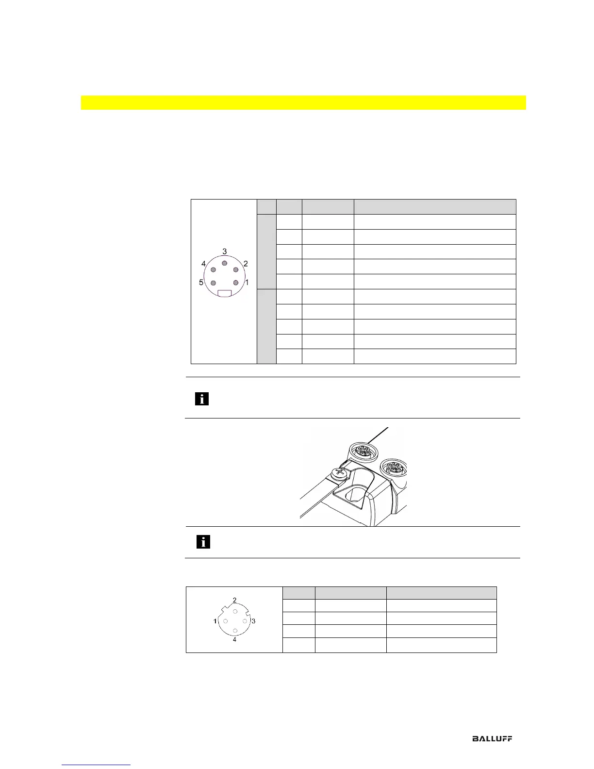
3.3. Electrical
Connection
Power supply
IN
Connector 7/8"
Pin
Function
Description
Class A
1
0 V
GND actuator supply
2
0 V
GND module / sensor supply
3
FE
Function ground
4
+24 V
Module / sensor supply
5
+24 V
Actuator supply
Class B
1
N24
Separate supply voltage (-)
2
0 V
GND module / sensor supply
3
FE
Function ground
4
+24 V
Module / sensor supply
5
P24
Separate supply voltage (+)
Note
Provide sensor/bus power and actuator power from separate power sources if
possible. The total current of the module must not exceed 9 A, even if the
module is looped through a circuit.
Grounding
Note
The functional ground connection between housing and machine must have a
low impedance and be as short as possible.
EtherCAT™
interface
M12, D-coded, female
Pin
Function
Description
1
Tx+
Transmit Data +
2
Rx+
Receive Data +
3
Tx-
Transmit Data -
4
Rx-
Receive Data -

Table of Contents

Questions and Answers:

Question and Answer IconNeed help?

Do you have a question about the Balluff BNI ECT-507-005-Z040 and is the answer not in the manual?

Balluff BNI ECT-507-005-Z040 Specifications

General IconGeneral
BrandBalluff
ModelBNI ECT-507-005-Z040
CategoryControl Unit
LanguageEnglish

Related product manuals