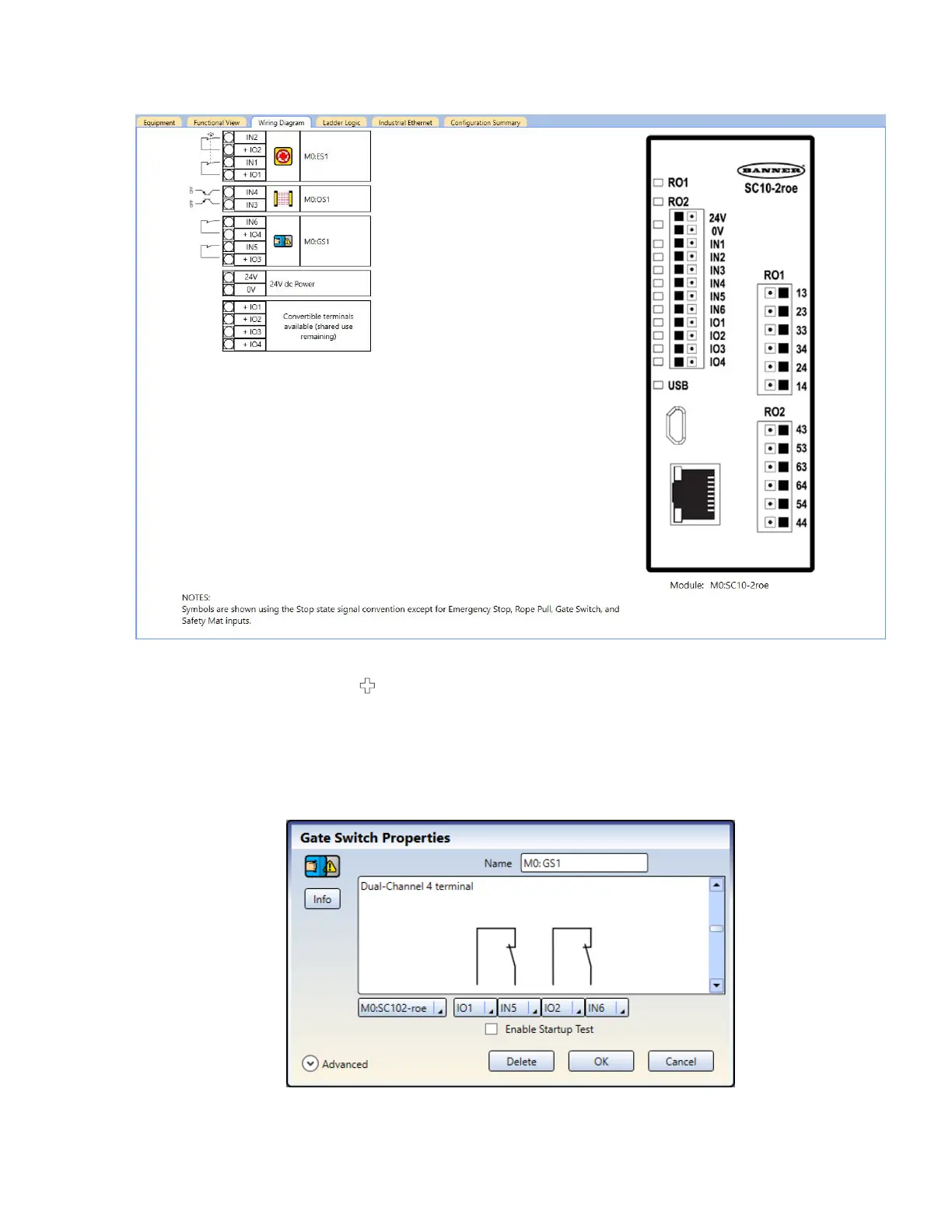
10. Go to the Wiring Diagram tab, and notice the terminals that are used.
Figure 112. Wiring Diagram tab with an E-stop button, optical sensor, and gate switch
11. Go to the Equipment tab and and try to add another Gate Switch.
No other equipment can be added (
does not appear) because the ATO feature is disabled and there are not
enough terminals to support more equipment.
12.
Go to the Functional View tab and try to add another Gate Switch.
No other equipment can be added here either because the ATO feature is disabled.
13. Click Cancel.
14. On the Functional View tab, click on the Gate Switch and then click Edit to change the properties.
a) Change the IO3 and IO4 terminals to IO1 and IO2 respectively.
Figure 113. Gate Switch Properties
b) Click OK.
XS/SC26-2 and SC10-2 Safety Controllers
www.bannerengineering.com - Tel: + 1 888 373 6767 139
 Loading...


